All,
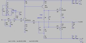
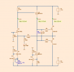
I have just made yet another incarnation of this amplifier that I think looks very promising. You may recall that I wasn't impressed with the JFET front end and BJT VAS. Well that was when I thought I needed a lot more drive for the fets so I was using the BD140. This one uses the BC560, which I think the JFET will have much less trouble driving.
Note that it needs no compensation, just a very small output snubber to keep it clean with no load attached.
Check out that 20kHz square wave into a 8R load at nearly full power...perfect!
I need to get some more current through the jfet, but my current dual led bias arangement won't let me as I can't turn on the JFET hard enough to get enough current through a smaller drain resistor. Will add another LED tomorrow so I can get enough voltage drop across a smaller resistor (like 150R or so).
Anyway, will post listening impressions tomorrow. I think it could be quite good!
Attachments
Last edited:
Mikelm,
To answer your questions.
No, I have never tried parallel ZVN3310s. Might be worth a go, but I really have a thing about paralleled devices, similar to your capacitor phobia. It is probably completely unwarranted though.
Actually, I have just realised over the last few days the audible affect of global feedback on the sound, and this perhaps makes some of my comparisons not completely equal. Now I understand this was a mistake and I will try to stick to a universal value from now on.
I have to say I think the amplifier sounds better with less feedback. I was trying hard to get the ideal amount of gain to suit my needs. I wanted to just be able to make the amplifier clip with a 2VRMS input. If I could not get it to stabilise I would then reduce the feedbeck until it did.
Now I can see this was a bad idea, as the feedback can really change the sound.
The 200kHz monster I posted a day or so ago sounded pretty clinical at first. But when I reduced the feedback (can't remember what to exactly, can check if you like), everything just came to life. It was like the amplifier could suddenly breathe. With the original circuit I was sitting there very analytically thinking "yes this sounds very good". When I dropped the feedback it induced foot tapping. The difference in perception was very apparent.
I am now going to stick to a 1:15 ratio for the feedback network for all future designs. Does that sound like a good compromise?
I'm sorry for my non apples with apples comparisons. I can now see that I wasn't rating everything on an equal footing.
In any case you're bound to decide on a different final design to me, I just hope the baseline I have provided you with is a good start for your project.
How is it coming along? Have you put iron to solder yet?
All,
Please forgive me for all the continual scope shots. I'm a scientist by trade and I love playing with scientific instruments. I hope you guys get as much out of this a I do.
The schematic I posted in post #1001 is looking very good indeed...on paper at least. I have dropped the jfet drainn resistor to 200R and added another LED to the bias stack. Oh, the input cap is 2.2uF too.
I did not think 7mA would be enough to drive the laterals that well, but check out the 100kHz square wave into 8R! Not bad at all!
Also attached is the 30V p-p 1kHz fft. Is this quite good for a lashed up amplifier sitting on the floor of my room with computers and other gear lying around?
Attachments
Last edited:
This is a fascinating thread. Much more civil interplay between the engineering approach of "wire with gain" and some deliberate seasoning. I think it's assumed that the issue that triggers conflict, is that it's considered bad engineering to stop short of lowest distortion and perfect stability. But a big part of the hackles rising, is just that scientific methodology may be ignored. This needn't be the case. Because, although it's often not, seasoning, and conclusions arising from experimentation can be done from an engineering perspective. After all, the objective is not to make an instrument (as in measuring instrument) amplifier, but to create a stable, long term illusion that makes us let go and enjoy "they are here", or "we are there" - without sacrificing accurate tonality.
What is required is an attempt to systematically study different modifications and gather data on how their interactions can be predicted to a degree. The present project is ideal for that, because of its bare bones simplicity. It's going around in circles a little bit, but that's OK. It would be terrific if what has been learned (even tentatively) can be summarized down the road a little. Wahab's amp might represent the maximum measured fidelity end. And, the various changes and incarnations given a subjective analysis of the specific ways that loosening up the amp modifies the illusion (remembering that we never listen to an amp, but to a system in a room, or headphones). This won't be completely definable, but it's reasonable to try, with appropriate qualifications. It should be remembered that the stereo illusion is, for the most part, an artifact. When I go to live venues, and close my eyes, it harder to pinpoint the sound source that it is at home. For amplified music it's darn near impossible. But, we don't need it in the live venue, because our eyes coordinate with our ears and fill in the missing or garbled information. We need the image illusion less for video, for the same reason. So even though stereo imaging is largely artifact, it is a very useful one, and makes the reproduction more accurate, in the sense that it fools us into believing we are witnessing a live performance - which is the point after all. Same probably applies to a little added timbre.
BTW, my observations from afar, and through watching various wrestling of this issue, is that distortion and distortion profiles don't seem to be the only seasoning. More than one person has suggested that perfect square waves and perfect stability seem to weaken the illusion (as mentioned above). This is not just with SS: http://www.diyaudio.com/forums/tubes-valves/138356-worth-using-anything-other-than-dhts-preamps.html I don't think that distortion is the issue in this citation, because the profiles can be made virtually identical for various tubes. I suspect that some physical parameter, such a microphony in the right amount and right frequencies adds a little touch of realism. Might be the same with a little ringing in the right place and right time.
Carry On
Last edited:
Sheldon,
Thank you for your insightful comments.
Yes, you are right, we are going around in circles a bit and this is mostly due to the fact that I am currently the only active builder (as far as I'm aware). Unfortunately I am perhaps not the best person to take things forward in a logical and systematic fashion. I have only been into this hobby for a short time and am still full of excess enthusiasm.
I try something and then think "I wonder how that would go with a bjt/MOSFET/ccs/bootstrap/bigger cap/smaller cap/etc/etc." Next thing I know I have a completely different amplifier!
However convoluted the road may be, I assure you we'll get there in the end!
I also think there have been some good examples here where simulations have supported listening impressions.
Anyway, I hope you continue to enjoy this thread. It has been a very interesting and educational exercise. Soon mikelm will have an operating amplifier and we can move forward in a more logical fashion. Can't wait!
I have to say I think the amplifier sounds better with less feedback.
One point about terminology for clarity of discussion:
If OLG = 100dB ( x 100,000 )
and CLG = 24dB ( x 16 )
then there is 76 dB of "feedback"
So if OLG stays constant and CLG is decreased then the feedback has increased.
or to look at it another way if CLG stays constant then the "feedback" increases as the OLG increases or decreases as the OLG decreases.
So when I said you seem to like high feedback I was not talking about CLG.
You may know all this already, but I wasn't sure
cheers
mike
p.s. I don't like caps coz I tried amps with & without them and heard the difference
")
Last edited:
Yes mikelm,
I understand the feedback terms. I prefer the sound with less feedback (more CLG) and no compensation, over less CLG ( and more feedback) with compensation. Once you hit a CLG of 10 or so it seems almost impossible to get stable without significant compensation. I now prefer to have more CLG (less feedback) with no compensation, though I didn't make the connection until a few days ago.
Btw, my capacitor comment was not intended as a stab at you so I hope you weren't offended. I was just saying that I have a weird thing about paralled devices that is probably completely unjustified, and I feel as strongly about it as you do about capacitors. It just doesn't feel right for some reason. I'd rather use a larger device. Weird huh?
I'm not sure you want to drive output MOSFETs directly from VAS & Spreader.
Cause Miller capacitance grows crazy near the rail, when the drain loses bias.
And the bootstrap implies your intent "to go there". I think you may need EF
stage between spreader and output gates... Else you don't know what goofy
unsimulatable currents are flowing across spreader resistor due variable CGD.
Then again, you got big feedback loop. And this problem doesn't much affect
the behavior at crossover, where CGD is better behaved...
Last edited:
I think it's best to choose the CLG you need and engineer the OLG to give the amount of FB such that compensation is hardly needed.
Of course, manufacturers are duty bound to make amps that are stable with any load, which might mean they sound less than optimum with any particular speaker.
As DIYers we can engineer our amps to sound most ideal with our own speakers which I think gives us a distinct advantage.
Why should our amps have to be totally stable with 100nF when the load will never be more than 1nF ?
No offense what so ever - just thought it might be worth a try with doubling up
Mikelm,
I can see how I confused you. It's only the last few days that I have made the connection between feedback and sound quality. Prior to that I was striving for a clg that could just clip with a standard line level signal, or , failing that goal, the most feedback I could get and remain stable. I didn't like the idea of having to attenuate my source.
As I am only using 25v rails, this meant quite a lot of feedback.
Now however, i have realized, especially with the 200khz monster, that feedback has a profound effect on the sound, and I actually prefer to have more CLG (less feedback), especially if it means I can do away with compensation. I think you will find that the miller cap especially has a detrimental effect. I would recommend trying every trick in the book to avoid using one.
Anyway, hope I have cleared that up.
I think it's best to choose the CLG you need and engineer the OLG to give the amount of FB such that compensation is hardly needed.
up
Yes, I think this is a good idea and it's how I've gone about my last few iterations. It can be hard though! Today I tried 200r of vas degeneration with the zvp to no avail! Crazy huh?
It's taken me a while to get the workflow clear in my head, but now I have it. The last circuit I posted embodies everything I have learnt, please note that I have dropped the jfet drain resistor to 200r to u the current to 5ma.
I think it will be a winner. Stable with no compensation, but only just. Needs a snubber. Right on the edge. A gain of 16. Perfect for me. Peferct square wave with zero ringing. 100khz of easy bandwidth. Overall I'm pretty happy. Can't wait to hear it.
Hi,
Does anybody notice that OLG in SWF's amp seems to be heavily depending on output current, as the bootstrap still loads down the "current portion" of the VAS gate swing with 1k5? So at low (or even most of the audio) frequencies effectively the dominant current in the JFET is a scaled-down copy of output current, not output voltage. That is an interesting property of bootstrapping a VAS load resistor from the output voltage, especially with a loudspeaker load. EDIT : Note effect of snubber on it.
With a CCS'd VAS this "current portion" would see the same light load than the pure voltage swing and output current wouldn't be reflected back much into the JFET.
I tend to like current-dominated control loops better...
And yes, ...really the most exiting thread here in a while...
- Klaus
That is the way, mikelmI think it's best to choose the CLG you need
and engineer the OLG to give the amount of FB such that compensation is hardly needed.
To introduce a compensation cap effects not only stability.
We wish not have any comp cap.
Hiraga, JLH & Nelson Pass, all very little users of cap.
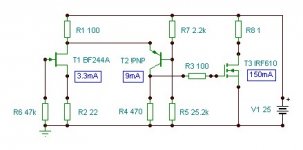
Classical amplifiers WITHOUT comp caps.
Schematic below is such an amplifier.
The feedback resistors are 3300/220/220uF.
I use no resistors for the IRF9610. No Gate, No source.
AC Analysis shows it should be stable without cap.
(2200/150 needs a small miller cap.)
I use IRF610 as Current source for the IRF9610 VAS.
This amplifier should have a good performance
and still probably a good sound.
Attachments
Yes, you are right, we are going around in circles a bit and this is mostly due to the fact that I am currently the only active builder (as far as I'm aware). Unfortunately I am perhaps not the best person to take things forward in a logical and systematic fashion. I have only been into this hobby for a short time and am still full of excess enthusiasm.
No apologies, it's an approach that has some advantages. Not very efficient if you know exactly what you are after. But I'm a scientist too and work this way often, particularly when something is new to me. I have a hard time sticking to a linear path. It's like diving into a pool and cruising around until I know the shape of things. When I feel have a rough grasp on the territory, and only then, do I buckle down and head for the goal line. If you get on the straight line path too early, you might miss a lot. Even if you don't understand at first what you are seeing, understanding can pop up when you don't expect it.
If you are in that half awake state early in the morning, and you are dreaming about this stuff, then you are doing it right.
I should add, that if you take wide ranging exploratory path, you should be careful to record as much detail as you can, and keep it organized. In the interest of full disclosure, this is not my strongest skill.
Sheldon
Last edited:
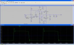
Moment of truth!
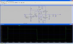
First of all, i am not trying to send the circuit to graveyard.
I have just put the circuit into the simulator. Or should we basicly.
I know that i have added input lowpass filter, DC voltage adjust, C5 is only 10uF and the Zobelnetwork is disabled (4.7Ohm + 1fF cap)
R13 is modified to 600 + 150R (RCOMP).
I have added a CCOMP of 1fF -> not active
I wanted to see how the circuit behave.
On the first picture the circuit oscillate and the load is 1MOhm pure.
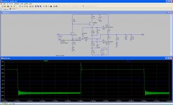
On the second picture the oscillation is removed by adding CCOMP of 100pF.
The slewrate is assymetric in both sims and just little smaller with CCOMP added.
On the third picture the load of 10nF||8R is added + CCOMP of 100pF + Zobel is 4.7R+22nF.
The Zobel is needed to add stability into capacitive loading as SWF,
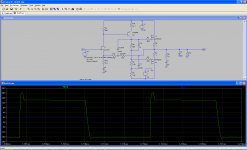
On the fourth picture the load of only 10nF is added + CCOMP of 100pF + Zobel is 4.7R+22nF.
All,
I have just made yet another incarnation of this amplifier that I think looks very promising. You may recall that I wasn't impressed with the JFET front end and BJT VAS. Well that was when I thought I needed a lot more drive for the fets so I was using the BD140. This one uses the BC560, which I think the JFET will have much less trouble driving.
Note that it needs no compensation, just a very small output snubber to keep it clean with no load attached.
Check out that 20kHz square wave into a 8R load at nearly full power...perfect!
I need to get some more current through the jfet, but my current dual led bias arangement won't let me as I can't turn on the JFET hard enough to get enough current through a smaller drain resistor. Will add another LED tomorrow so I can get enough voltage drop across a smaller resistor (like 150R or so).
Anyway, will post listening impressions tomorrow. I think it could be quite good!
First of all, i am not trying to send the circuit to graveyard.
I have just put the circuit into the simulator. Or should we basicly.
I know that i have added input lowpass filter, DC voltage adjust, C5 is only 10uF and the Zobelnetwork is disabled (4.7Ohm + 1fF cap)
R13 is modified to 600 + 150R (RCOMP).
I have added a CCOMP of 1fF -> not active
I wanted to see how the circuit behave.
On the first picture the circuit oscillate and the load is 1MOhm pure.
On the second picture the oscillation is removed by adding CCOMP of 100pF.
The slewrate is assymetric in both sims and just little smaller with CCOMP added.
On the third picture the load of 10nF||8R is added + CCOMP of 100pF + Zobel is 4.7R+22nF.
The Zobel is needed to add stability into capacitive loading as SWF,
On the fourth picture the load of only 10nF is added + CCOMP of 100pF + Zobel is 4.7R+22nF.
Attachments
Sonnya,
Interesting simulations, this is more or less exactly how the oscillation presents itself. However, the stability is much better than your simulation - 22nf doesn't faze it.
Also, won't all amplifiers with a single ended VAS have an asymmetric slew rate?
Going to go test the stability in more depth.
KP,
That 100KHz square wave indicates that driving the laterals ain't such a big problem. With a few pairs, and/or hexfets, yes, driving with an EF (like Workhorse, and in one of my amps, the NAKSA) is a good idea. In this case, horses for courses....
Sheldon,
Great post. Good to see engineers getting along with golden eared chaps.
Sonny,
All SE amps regardless will have asymmetric slew rate. As long as the lesser value is well over about 10V/uS this is no big deal. It does indicate that much of the distortion will be even order, but since this is (mostly) musical this is no bad thing.
SWF,
Maybe run the jfet at 2/3 of its Idss? The transfer curve is extremely abrupt at low currents, which would create lashings of H2/H3, so 5mA seems about reasonable?
In your attempt to build a VAS without compensation (indicating lots of degen and a very low transconductance front end and maybe a bootstrap chucked in to help with top end rolloff) you might be going a bit light on lag compensation.
In a bjt in particular, the quality of the parasitics in the device, which largely center around the depletion layer, are appalling. It's a leaky cap, essentially, with lousy Q. Yet this capacitance helps with the miller capacitance and is augmented by the real miller cap outside the device.
Some lag compensation is no bad thing, particularly if it is high quality, and I recommend silver mica. By using a LC cap, you tend to play down the poor quality of the internal parasitic cap. The next issue of course is to choose a good transistor; I have some KSA1142 Fairchilds I can send you. Email me your address and they are yours.
Great transistor, BTW.
Mike,
If the amp tests stable with 100nF//8R, then it's very, very stable, and will drive a 4" rusty nail. It's just a test.... Oh, and caps, particularly good ones, can be part of Sheldon's 'seasoning', it ain't all bad y'know!
Cheers,
Hugh
Last edited:
Sonnya, I think LTSpice tends to be very pessimistic regarding oscillation. Obviously the circuit doesn't oscillate this way in real life. Also you left out the gate stopper on the Jfet. SWF may have taken his tests with the input filter, I don't know if he removed it.
Also, add some .5R resistance to your supplies and some filtering just to make it more realistic. Add appropriate series inductances and resistances to all caps. Then the simulation may be more indicative of real life.
KSTR, you've noticed it about "current-dominated control loops" too..? I have found indications in the simulator this is how it should be. As it turns out, this is characteristic of amplifiers where OLG is flat throughout the audio spectrum, that is, dominated by resistances instead of reactances "less OLG, less compensation". I think such amplifiers also tend to be more stable.
Swordfishy, to decrease OLG you should probably try degenerating the Jfet. Degenerating the VAS simply makes the Jfet work harder, that decreases OLG but also increases distortion. Maybe it's time you start playing with the gate stoppers?
Juma, a few mV can make a big difference for a BJT, especially considering that these mV will contain the distortion of the output stage. Of course it may not matter (depending on whether this distortion is small compared to other distortions) always but when in doubt I tend to go for the lower number.
SWF, look at your square shots closer. I see some ringing on the lower corner. This may be unavoidable though.
- keantoken
I don't see stereo as an illusion, but as an attempted hologram. After all, it's not an illusion if you recognize it's not real. The mind after all is the final sensory organ, which can extrapolate the reality even if the senses themselves are fooled momentarily. The technology obviously is not complete or practical in terms of successful results, but still there are ways to improve it. The blacklevel can be raised or lowered, sometimes reds will bleed, bright spots will encroach on subtler adjacent hues, and so on. It's never perfect but it can still be better or worse.
At first we tend to think that good amplifiers help to create and illusion of security and a relaxed atmosphere, maybe inject some endorphins to get you to loosen up... This may be seen as be a way of escaping reality. But what if it's an unnatural environment that continually turns on our stress response, and the music is seen as a way to bring stress levels back down to reasonable levels? Stress kills.
To me, I like an amp that retains the edge, except the edge is not edgy. I find that listening to such an amp relaxes me, but doesn't shy away from realistic presentation. It helps me move into a state of relaxed vigilance, where I can think more calmly and objectively.
This is the effect I'm getting from a class A Pass-like thing I have running right now. Just two IRF250s (2nF!!!) biased about 800mA with 10R power resistors. They came with 1K gate stoppers, I lowered them to 100R, and that made a big difference. I am considering raising them a bit.
Am I close?
- keantoken
Hi,
here is what I had in mind, a J-FET transconductance input stage followed by a common base transimpedance stage, essentially having the same properties as the conventional cascode, but the latter offers additional advantages.
In the Hawksford cascode the voltage amplification is executed by a common base amplifier all right, but the intermediate grounded collector and grounded emitter stages only cause distortion.
The main properties of the common base amplifier:
¤ low input impedance
¤ high noise immunity
¤ high isolation between input and output due to
¤ low feedback factor
¤ high stability and wide bandwidth due to the absence of Miller effect
¤ wide dynamic range
¤ high input overload capability
¤ precisely controlled voltage gain
¤ current gain just below one (low power gain gives low distortion)
¤ the same amount of current flows through the input and output and in some configurations through the signal source (giving low distortion)
¤ no phase reversal between input and output
Attachments
- Status
- This old topic is closed. If you want to reopen this topic, contact a moderator using the "Report Post" button.
- Home
- Amplifiers
- Solid State
- JFET input, MOSFET VAS, LATERAL output = Perfect!!