Hi Hugh,
Please re-read carefully
This is not an accurate simulation for the reasons previously stated and restated below.
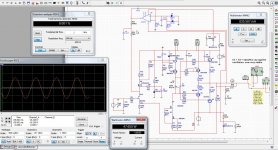
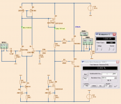
"Here is the somewhat simplified schematic that shows more or less what I'm listening to at present. Please ignore the actual parts - I switched to LT spice a while back and am finding it almost impossible to import parts - perhaps coz I'm running W7 on a MacBook - so I just use whatever parts are in the box to get an idea of what is going on. My output devices are still buffered lateral mosfets."
I used to believe that simple designs were the best designs but now, based on my own experience, I make my designs as simple as possible but as complicated as necessary to achieve a performance that sounds accurate and is not hard on the ears.
I think comparing this new input arrangement with a simple Jfet may be a classic example of how conventional measurement techniques don't get to the real significance of what is changing.
I wish you could hear it Hugh, because I think you would like it")
Please re-read carefully
This is not an accurate simulation for the reasons previously stated and restated below.
"Here is the somewhat simplified schematic that shows more or less what I'm listening to at present. Please ignore the actual parts - I switched to LT spice a while back and am finding it almost impossible to import parts - perhaps coz I'm running W7 on a MacBook - so I just use whatever parts are in the box to get an idea of what is going on. My output devices are still buffered lateral mosfets."
I used to believe that simple designs were the best designs but now, based on my own experience, I make my designs as simple as possible but as complicated as necessary to achieve a performance that sounds accurate and is not hard on the ears.
I think comparing this new input arrangement with a simple Jfet may be a classic example of how conventional measurement techniques don't get to the real significance of what is changing.
I wish you could hear it Hugh, because I think you would like it
Lineup,
could you add in an index to post1, of up to date sch & bom & PCB source etc, for new readers and us oldies that forget?
In this particular thread this is not really possible because the final consensus about this design has morphed away quite a bit from the idea in the first post.
I strongly support the unchanged buffered Q2 VAS though I'm not quite sure why you put in D1.
adding D1 enables a higher value 1st stage load resistor and gives more gain
Complementary mosfet master/bipolar slave double emitter OPS? WOW!! It is so reversed over the usual approach that I would expect it would sound very difficult.
Guessing you meant different - this o/p arrangement is used by John Curl and similar to the one used by Lazy Cat - havn't actually tried it yet but have just taken delivery of some boards that allow easy comparison of these different o/p stages
cheers
mike
Last edited:
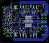
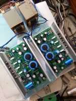
My idea was to one day to build this, a allfet version I have ideas from here, the DN2540 fets I have doubled, it give more room for cascode driving mosfets. distortion in sim drops with it, compared to a single one, but not al that much I did see.
This moment I do still use hybrid amp, and a new one who uses tubes with a compount amp, reason is I do want to have no feedback at all, so not cathode followers min or no source followers.
It did give interesting sound.
But I think also there is almost everything tryed to get new topologies, the new Jfet power transitors will maybe give new idea,s.
Pictures are fet amps a la diyaudio, I did sim some more idea,s in it, so I am a fan of currect feedback to prevent nasty TIM, and it give a fast wide amp,
only drawback is it is not so offset stable, and so the first has a servo, I try first the one withoud servo, to see how it drifts.
Attachments
Last edited:
I have no idea what posts have the circuit and PCB, BOM to the actually final stuff.Lineup,
could you add in an index to post1, of up to date sch & bom & PCB source etc, for new readers and us oldies that forget?
If somebody knows I would add an index in post #1.
Maybe in the forum of AKSA, there is all we should know?
Have o look here and look for FETZILLA: AKSA - diyAudio
If every Source had a buffered output, then we would not need this conversation.
Not every source actually needs an output buffer, usually the source impedance is low enough.
I suppose I wouldn't have any problem either if I did not usually have to use volume pots. That's really the only reason source impedance would be very high.
I could build a universal buffer onto a universal volume pot to use while testing my amps, but the thing is, the buffer takes SO much fewer parts if you just build it into the amp. A buffer built into the amp is far more economical than a buffer built onto the volume pot. It is both economical and it doesn't put so many requirements on the source if it's directly connected, so I see it as an advantage in many ways.


Attachments
My idea was to one day to build this, a allfet version I have ideas from here, the DN2540 fets I have doubled, it give more room for cascode driving mosfets. distortion in sim drops with it, compared to a single one, but not al that much I did see.
This moment I do still use hybrid amp, and a new one who uses tubes with a compount amp, reason is I do want to have no feedback at all, so not cathode followers min or no source followers.
It did give interesting sound.
But I think also there is almost everything tryed to get new topologies, the new Jfet power transitors will maybe give new idea,s.
Pictures are fet amps a la diyaudio, I did sim some more idea,s in it, so I am a fan of currect feedback to prevent nasty TIM, and it give a fast wide amp,
only drawback is it is not so offset stable, and so the first has a servo, I try first the one withoud servo, to see how it drifts.
do you have any idea about which simulation software has been used ?
Last edited:
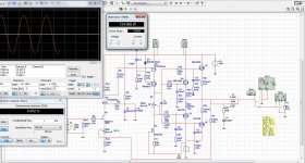
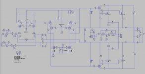
Here a new take on JFET input, MOSFET vas and MOSFET output.
It does 48 Watt RMS before clipping in Class AB (bias is 200mA).
The only bipolar are the drivers: 2SC2911/2SA1209
I use them drivers to get 12 mA onto gates of IRFP240.
Power supply are trafos 2x24 VAC, 200VA for +/-35 Volt rails.
One trafo for each channel.
To setup you need to seek a resistance R8 that give ~5 mA through your JFET 2SK170BL at 35 Volt
Then chose feedback resistor R9 for gain like x20
After this you can adjust R1 (632 Ohm) for zero at output.
Then adjust R4 (4.95 kOhm) for 200 mA in the output devices.
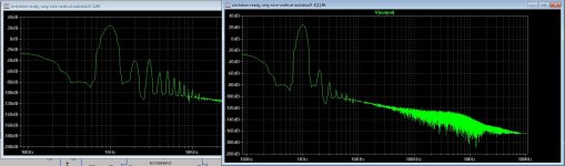
Performance.
THD at 1 kHz is low.
0.0008% at 1 Watt
0.0060% at 42 Watt
The good thing is that 2nd harmonic is very dominant at all levels.
The sound is probably very MOSFETish!
Enjoy
would like to know the name of simulation software which you have used to create this schematic .
do you have any idea about which simulation software has been used ?
I did use multisim.
IH5020-SRPP
IRF610
2SK1058/2SJ162
View attachment 508714
View attachment 508715
View attachment 508716
Attachments
Crude heard about, because time is short, may not be accurate, the first impression is good:
****Basic circuit is single-ended tube amp sound at the end, Naiting not noisy people, the density of the sound is good, small volume under can still have a good performance, but better than the kind of advanced single-ended tube amp tube amp just does not unique "Empty inspiration." More balanced tri-band, low frequency control better, voluminous music appears, musical interpretation of the relatively clear, high-frequency a little dance movement, seems sound and energetic.
****Because the circuit is not yet fully open burning, high-frequency slightly rough, loose bass are somewhat less degree. In our listening more than one hour, the feeling evident in the positive development of the low-frequency loose gradually improved, high-frequency gradually delicate up, but have not heard enough, it was the machine he hold back.
****In addition the machine a little quiescent current, the source resistance of the output tube using a 0.33 ohm, then forget the quiescent current test, but feel quiescent current should be less than 120MA. Then drive 4 ohm speakers, working more than one hour small volume, there is little cooler temperature, it seems have heard for some time, we have to adjust the quiescent current.
****Coupling capacitor using the ROE 1UF green film capacitors, may require a oil capacitors in parallel polish it.
This is the most perfect amplifier I have spiced.
It is simple but yet very, very good.
- JFET input with minimal offset problems.
- MOSFET VAS for speed and gain
- LATERAL output for be a light load to VAS
When CLass AB operation, 350mA bias, it shows only
THD 0.00018% at 1 Watt
And there is almost no increase of THD at 25 Watt output
Enjoy!!
---------------------------
EDIT:
For more building the final stuff and details, look for FETZILLA
in this AKSA forum: AKSA - diyAudio
Can we use this like a preamp with +/-20V with IRF610 and IRF9610 in output and a hexfet based Vbe Multiplier?
Attachments
Can we use this like a preamp with +/-20V with IRF610 and IRF9610 in output and a hexfet based Vbe Multiplier?
Poor 2sk1058 mosfet, he wil glow red
Ohh it is one watt I see.@kees52
Dear kees52,
the topology could be utilized for pre-amp driver stages.
I would recommend to use different MOSFETS to the IR's though. (I find them 'fuzzy' sounding..).
Zetex has some good parts as well for this purpose.
You basically need some with relatively low on Vgs-Voltage and they do not have to have 'outrageous' high Vds-voltage ratings for Your intended +/- 22V use.
50 Vds types will do just swell here.
More importantly - You should look for the most linear transfer curve 'ones', without to much Gate capacitance - as to not make life to difficult to the presiding stages.
Best for it
a1gd
Dear all,
please look at having a gate resistor for the Vas MOSFET instead of the Band limiting C2-Capacitor. The overall stability pole is better employed at the input LTP pair.
This all best done by simulating Circuit in OL-Open loop response mode.
Just me humble '2-cents suggestions'...
Best 4 it
a1gd
please look at having a gate resistor for the Vas MOSFET instead of the Band limiting C2-Capacitor. The overall stability pole is better employed at the input LTP pair.
This all best done by simulating Circuit in OL-Open loop response mode.
Just me humble '2-cents suggestions'...
Best 4 it
a1gd
Good idea having a gate stopper resistor onto MOSFET U7.Dear all,
please look at having a gate resistor for the Vas MOSFET instead of the Band limiting C2-Capacitor. The overall stability pole is better employed at the input LTP pair.
This all best done by simulating Circuit in OL-Open loop response mode.
Just me humble '2-cents suggestions'...
Best 4 it
a1gd
Capacitor should only be used as the final choice.
Because they are un-linear.
Better use the input capacitance in the MOSFET together with Resistor to shape the circuit behavior.
Dear kees52,
the topology could be utilized for pre-amp driver stages.
I would recommend to use different MOSFETS to the IR's though. (I find them 'fuzzy' sounding..).
Zetex has some good parts as well for this purpose.
You basically need some with relatively low on Vgs-Voltage and they do not have to have 'outrageous' high Vds-voltage ratings for Your intended +/- 22V use.
50 Vds types will do just swell here.
More importantly - You should look for the most linear transfer curve 'ones', without to much Gate capacitance - as to not make life to difficult to the presiding stages.
Best for it
a1gd
This is a time back? I am busy with a circlotron with mosfet vas, can you guys take a look? I have low output distortion, but it does have high distortion on the vas side and even more on the long tail pair input.
Maybe I did something wrong, or can do better.
I have use the phillips bsp225 types, have 2 volts gate on voltage. I have 65 + 65 supply on prestage because it needs 16 volts above circlotron output, maybe the cascode vas has high impedance and can not drive output well.
Practice is not problem for me, but the dieper knowledge is, I never had school for electronics, I did learn on mine own, en still see new things, class D is not a problem for me.
thanks in advance.
Attachments
- Status
- This old topic is closed. If you want to reopen this topic, contact a moderator using the "Report Post" button.
- Home
- Amplifiers
- Solid State
- JFET input, MOSFET VAS, LATERAL output = Perfect!!