Hey guys, this is my first real post in the SS forum.
Just got my "Blameless" Self/Sloan amp up and running and thought I'd post it. I was running a 2*50W Gainclones, but I felt like a new project and thought I'd build something with the potential for a bit more power. I haven't made any detailed measurements of distortion yet, but I will do so and post results if there's any interest. For what it's worth, it sounds great.
There's no DC servo, even without DC offset was about 9mV. It runs pretty quiet aside from some weird triangle wave shaped noise which I'm pretty certain was coming from the switcher in my PC which was sitting right next to the amp; posting a pic, if anyone has any other ideas about what it is please speak up. I won't be able to test properly for noise until I've built a sold power supply for it and can box it up properly with some shielding.
In the image, its running on 17V rails, with a small heatsink for testing puroposes.
I designed the single sided PCB layout with EagleCAD and etched it by hand. I'll post the layout if anyone is interested.
Attachments
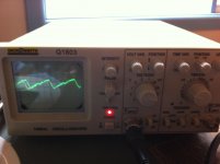
If I am reading the settings of your scope correctly, the sawtooth wave has a period of 20mS, that is, its frequency is 50Hz. If that's the case, it's coming from your amp's power supply.
Agreed... and probably from input/feedback return grounding points. The output should have no identifiable 50/60hz component when the input is shorted to input ground, even with significant ripple on the rails.
Hi,
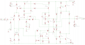
the input resistor, R5=10k, that defines Rin may not be exactly 10k.
It might reduce the output offset by lowering R5 slightly or raising R5 slightly.
It is easy to check this.
Let the amp warm up monitoring the output offset. When it is stable, add an extra resistor across R5 in parallel. try 100k. Does the output offset increase or decrease?
If the output offset decreases trying adding a lower value resistor, try 47k. Keep going till you find the value that gives the lowest offset. I doubt you will need to go lower than 8K (=10k//39k).
Alternatively if making R5 lower increases output offset then you can try increasing R5.
This is not so easy to keep re-trying by trial and error.
Instead remove 10k and fit 12k. Measure the fully warmed up output offset. Has the output offset increased or reduced. try adding 100k in parallel. Is output offset higher or lower.
I am not doing this to minimise output offset which it does very effectively. I am suggesting this in the hope that you can increase Rin above the 10k value that you have at present. This is very low by domestic standards and limits the usability of the amplifier. You might find that 10k5 gives zero offset. or 11k2 or some other value.
If a lower than 10K Rin gives lowest output offset, you can consider swapping T1 and T2
to find the new Rin for lowest offset.
BTW,
bc556a does not make a good input transistor. The low gain results in high input offset current and this gives high voltage across Rin and also leads to higher than needed output offset. Try to find equivalent transistors with gain >400. Some types go over 1000 hFE, but they are more difficult to source and generally much more expensive.
bc556c and bc560c are generally in the range 400 to 600 hFE.
T10 and T8 look like they are running very warm. Attach flag cooling or replace with >=1W devices.
A few more details about how the measurement with the cro was done would be good ") It is the output of the amp that it is showing right?
It is the output of the amp that it is showing right?
The fact that it is 50 Hz is interesting in itself (to me) I'm assuming you have a full wave rectifier, normally you will get 100Hz ripple if you have full wave rectification. Assuming a dual secondary transformer, If the secondary's are wired out of phase though you will get 50 Hz ripple. You can check this by measuring the AC voltage across the bridge, if it is zero volts then the secondary's are wired out of phase.
The other thing that is interesting is how clean the waveform looks, apart from the 50Hz sawtooth there doesn't appear to be any other "noise" at all! It looks more like the output of a well filtered power-supply to me!
Tony.
It is the output of the amp that it is showing right? The fact that it is 50 Hz is interesting in itself (to me) I'm assuming you have a full wave rectifier, normally you will get 100Hz ripple if you have full wave rectification. Assuming a dual secondary transformer, If the secondary's are wired out of phase though you will get 50 Hz ripple. You can check this by measuring the AC voltage across the bridge, if it is zero volts then the secondary's are wired out of phase.
The other thing that is interesting is how clean the waveform looks, apart from the 50Hz sawtooth there doesn't appear to be any other "noise" at all! It looks more like the output of a well filtered power-supply to me!
Tony.
Thanks for the feedback guys.
The 50hz hum might be the result of the power supply I had it running off at the time; it was a poorly built and badly laid out PSU I built a while ago for something else with a transformer I'd pulled out of a broken amp I came across. The grounding on the PSU board itself is poor and as suggested the trafo winding may be in the wrong phase. (Yeah, that was the output of the amp Tony.)
Andrew T, the lower than usual input impedance is recommended by D. Self to, if I recall correctly, reduce the amound of interference/noise the input stage picks up by using lower Z nodes. I'm probably going to run it with a preamp that I'll make sure is punchy enough to drive the lowish input impedance.
The input transistors are BC546C's, I agree that higher beta would be better though. I pretty much just used them because I wasn't sure how high I'd end up making the rail voltages, so I used high voltage transistors throughout.
Yeah T10 and T8 are running kinda close to maximum spec, I'll see how they go.
In regards to reducing the output offset, I probably won't bother to try, 9mV really doesn't worry me.
Yeah, I understand that. They're rated at 500mW and they're dissipating less than 250mW. That doesn't worry me too much. The don't seem to be getting too warm, but if they do I'll replace them.
That isn't what's being said here. The transistor can cope with 500mW when @ or below 25 degrees C.
The case style will increase in temperature by 250 degrees per watt.
Given 17 volt rails at a CC of 6.7 mA you are indeed looking at 0.11mW, which will result in the transistor running at around 45 degrees, which is not worryingly hot to the touch.
However if you increase the rails up to 30 volts, necessary for 50+ watts @ 8 ohms and you're looking at around 200mW. This will increase the transistors temperature by 50 degrees, add in an ambient of 25 degrees and we're up to a 75 degree working temperature.
These transistor types can typically handle around half their rated power @ ~75 degrees.
This will probably be fine run outside of a case, where it will experience pretty decent convection cooling, but put inside a case, where the ambient temperature will be higher and you've got a potential situation on your hands.
But if they do I'll replace them.
This is the wrong attitude as it implies you're already running them under the circumstances that would necessitate a change, ergo they could explode before you realise they are running too hot. Or you could burn yourself when seeing if they are too hot.
We've all been there at least once before anyway, just be warned that the VAS and CCS transistors will require heat sinks if any decent reliability is to be expected, when run at higher voltage rails and when inside a case.
I think that the choices you have made for devices is fine for testing and prototyping. there is noting like getting your hands dirty to get your head around things and learn some tricks.
That said, in a power amp of more than a few tens of watts, I would use a somewhat more robust transistor for the Vas and current source as discussed above.
In Australia your local shops (Jaycar, Altronics etc) just don't stock good devices for use in Vas (T8). I suggest that you look on EBAY for a good Vas transistor. I have very successfully used 2SC2682 - look on other forums for a wide range of other options.
For the PNP current source, (T10) I suggest you consider the MJE350 which works fine and is easily available.
With this change the issue of power dissipation goes away - as does the upcoming issue of voltage rating which is yet to be raised.
Why voltage rating? for 50-60Watts, you will be looking at rails of > +/-40 Volts. Which will result in peaks of 80 Volts on T8 and T10. Not a happy place to put a BC556 in!
A question though - what led to the decision to use TIP2955 / 3055 as output devices?
If you used the commonly available MJL21193/4 your would get better Hfe, easier loading on the Vas stage (perhaps allowing you to drop the standing current and ths dissipation) and possibly less distortion. These devices ARE available easily at your local electronics shops in Australia. By the way, the MJL21193/4 are very - very rugged in the deal.
For the moment the amp is sitting on the bench. which could indeed by why I haven't had any power dissipation problems with the VAS transistor. Once I find something suitable, I'll replace it. What I'm looking for is something with high Hfe, >80v voltage rating, low Cob and decent power handling yes?
I used TIP2955/3055's because (at jaycar at least) I could get 4 pairs of them for the price of one pair of MJL21193/4 and wasn't totally confident the thing wouldn't just blow up as soon as I powered it up.
I'm thinking this one might become a guitar amp where the slightly increased distortion won't bother me, but I like this amp and will probably build a couple more for proper stereo service in which case I'll definitely use MJL21193/4.
Thanks for the feedback guys.
Googlyone, wouldn't i get 60W out of roughly +/-32V rails? I thought +/- 40V would give close to 100W of sine power?
Last edited:
If your amplifier can put 40 volts peak across an 8 ohm load, you will get 100W sine power. The problem in practise there are inefficiencies and losses - and from the perspective of an amplifier the ratings of devices need to consider unloaded and loaded conditions.
What does this mean? I won't try posting a whole amplifier model (I have a heap of spreadsheet type analysis I use in designs - but they make MY eyes water...) A few things you need to worry about are:
To get 100W into 8 ohms, you are right, you need 40V pk.
- At this point you have 5 Amp peaks
- Your power supply will typically be a transformer / bridge / capacitor arrangement. Assuming a decent toroid, big bridge and modest capacitor bank (say 10,000uf for a 100W amp) you will see rail droop in the order of 6 or 7 volts from the unloaded condition. (seems like a lot? it is!)
--> From loaded to unloaded supply you need to budget 7 volts droop. Larger capacitors help, as will a larger transformer - but reality is this is life.
- Your amplifier cannot get the output to the supply rail. In your design the use of CFP output helps, but there is the best part of 1 volt drop on the "VBE" of the compound output pair, plus the voltage drop across the emitter resistor, 0.5 volts for 5A pk. Then you have the Vas stage on the bottom half, and current source load for the top half. This can be driven to saturation - and can in fact get to closer than you might think to the supply rail, but is still the best part of 0.6 Volts (have not looked too closely here).
- So you wind up with the Amplifier being able to drive to within a couple of volts of the supply rail under load.
Where are we at:
- Supply rail droop 6 or 7 volts
- Amplifier capacity to drive to rails 2 volts
A 100 Wat amplifier needs 40V pk on 8 Ohms, so is looking for a supply rail of +/-50 Volts. huh? Yep that is the way it works.
Not sure of your age - I think you are Australian though - If you recall the Series 5000, used 50 volt rails for a 100 Watt amplifier. There were plenty of 50 and 60 watt amplifiers (ETI480, 477, silicon chip copy of 480) these used +/- 40 volt rails for a 50-60 watt amplifier.
Crazy big supply capacitors is one way to address this in part, but is expensive and ultimately causes other problems. Simply upping the unloaded supply rails and considering power supply loses in the design is the only sensible approach. The design of an "amplifier" is thus more than the circuit of the power amp itself, you need to look to the whole chain.
Happy to discuss further if you want.
When you spell it out like that it makes sense!
I just measured my rails while turning the amp up fairly loud and they did droop by almost 3V even with 10,000uF of capacitance per rail (well 9400uF really, I prefer to use a number of smaller caps than individual big ones, its cheaper and gives less series resistance), and although I didn't actually measure the output, I probably realistically wasn't pushing it very hard.
A couple of questions though, when you say that the Vas/ current source can be drive to saturation, are we talking in terms of current saturation starving the bases of the driver transistors? If so, that could be prevented by using a high enough current in the class A VAS yeah?
I'll have to get myself a few MJE350's for current sources. I'm guessing the reason you don't recommend these as VAS transistors is low Hfe? Sounds like I'll also have to invest in a big 50V toroid if I want to make it to 100 real watts.
Also, do you know of any good sources for valve transformers? I've been thinking about building a valve amp for a while but it seems hard to find any reasonably priced locally.
The Voltage Amplifier Stage can go into saturation - by which I mean there is more current into the base than needed, and the Vce is at saturation (small fraction of a volt). Your schematic (from memory) included a transistor sensing the Vas emitter resistor voltage - this transistor is there in no small part to ensure that the VAS is not driven too hard. This is an important and often missed protection component.
--> Your current in the Vas is OK - increasing it for a 100W amplifier is not necessary.
MJE340 will "work" as a Vas transistor. The issue is more Cob and Ft. I have built amplifiers and used these - the effect is a bit of "sticking" on negative rail clipping (put one in and try it) and and an interesting effect on stability at high current near negative rail - which turns up as little bursts of oscillation at large negative excursions and high current.
BF469 / BF470 are older video transistors that are appropriate and quite likely available at your local shop.
The transformer you should be using for 100 Watts is likely to be about 36-0-36 VAC. Will rectify to close to 50-0-50.
I don't do valves. (Sorry tube heads!)
- Status
- This old topic is closed. If you want to reopen this topic, contact a moderator using the "Report Post" button.
- Home
- Amplifiers
- Solid State
- "Blameless" style ~100W amp with CFP output.