Hello,
I’m restoring a Musical Fidelity A1 amplifier. I’ve read with great interest various threads here and in other websites and I have several ideas that I’d like to confirm before ordering several components (now I’m in the period of gathering data and part lists).
1) Loudspeaker protection
It seems that is very important to have some kind of loudspeaker protection at the A1’s output, to avoid any risk to the loudspeakers (on-off noises, DC offset). There are several kits for this, like the Velleman K4700 (that seems useful, well made and good-sounding, specially with a better-specced power relay) or the one made by Thel.de. These protection modules cut the connection between the A1 output stage and the output binding posts during several seconds at turn-on and –off and if there is DC present above certain level (I think that +/-1Vdc). However, Musical Fidelity advises specifically that the A1 must have a load connected at the output and must be connected always to the loudspeakers before switch-on.
Are those 5-6 second of disconnection at turn on/off are dangerous for the amplifier? If so, I think that any risk could be avoided by soldering a pair of suitable power resistors (8 ohms/20w or so) to the other output of the protection relay, the one to which the amplifier output is connected at turn on/off. This way, the A1 will be always connected to a load: the loudspeakers in normal use, or these power resistor in malfunction and at turn on/off. Is this correct?
2) Bias/heat management
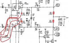
One of the bigger problems with the A1 is the enormous heat it generates. Although I’ll use a heatsink much bigger than the original, I’m still concerned with the heat and the power consumption. In the A1, the quiescent current is set by several resistors: R6, R11, R30 y R31 (see attached schematic). My A1 uses 3M7 ohms in R6-11 (small metal film) and 0R22 ohms in R30-31 (big output resistors), but other units have different values, respectively 1M8 (or 2M7) and 0R47, with apparently no reduction in sound quality.
What do you think about using 1M8 and 0R47 values, for lower quiescent current and less heat?
In one of the A1’s threads here at diyaudio there is a very interesting suggestion. When R6-R11 are out of circuit, the quiescent current is only 10% from the original. The sound quality obviously will suffer, but for casual listening probably it’s more than enough. My plan is to use a few cm (max. 20cm) of wire and a 4-pole toggle switch in the front panel, to use or not the two R6-R11 resistors per channel: “in circuit” (class-A) for critical listening, and “out of circuit” (class-B) for background music/radio/stand-by mode.
Is the wiring in the schematic correct? Do you think that is possible to operate this switch with the amplifier on (perhaps without music playing or with volume to 0) or there is any risk of clicks/noise?
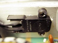
The A1 has a thermal cut-off (see picture) soldered in series with the AC live wire, after the fuse and before the front panel ac switch. It is fixed, with screws and thermal paste, to the aluminium U-channel that joins the output transistors and the heatsink. I haven’t found the exact replacement, but there are equivalent thermal “switches” that open when reach a preset temperature and cut the 240V ac supply, turning off the amplifier if the heat is excessive. From what I have read, I think this temperature is around 70ºC for the A1, so I think this “Stancor 3L11-170 temperature sensor” from Mouser (ref. 802-STO-170), that opens at 74-79ºC, or this thermostat from RS (ref. 229-5884), that opens at 70ºC, are appropriate. Am I right?
Thanks in advance for your help
I’m restoring a Musical Fidelity A1 amplifier. I’ve read with great interest various threads here and in other websites and I have several ideas that I’d like to confirm before ordering several components (now I’m in the period of gathering data and part lists).
1) Loudspeaker protection
It seems that is very important to have some kind of loudspeaker protection at the A1’s output, to avoid any risk to the loudspeakers (on-off noises, DC offset). There are several kits for this, like the Velleman K4700 (that seems useful, well made and good-sounding, specially with a better-specced power relay) or the one made by Thel.de. These protection modules cut the connection between the A1 output stage and the output binding posts during several seconds at turn-on and –off and if there is DC present above certain level (I think that +/-1Vdc). However, Musical Fidelity advises specifically that the A1 must have a load connected at the output and must be connected always to the loudspeakers before switch-on.
Are those 5-6 second of disconnection at turn on/off are dangerous for the amplifier? If so, I think that any risk could be avoided by soldering a pair of suitable power resistors (8 ohms/20w or so) to the other output of the protection relay, the one to which the amplifier output is connected at turn on/off. This way, the A1 will be always connected to a load: the loudspeakers in normal use, or these power resistor in malfunction and at turn on/off. Is this correct?
2) Bias/heat management
One of the bigger problems with the A1 is the enormous heat it generates. Although I’ll use a heatsink much bigger than the original, I’m still concerned with the heat and the power consumption. In the A1, the quiescent current is set by several resistors: R6, R11, R30 y R31 (see attached schematic). My A1 uses 3M7 ohms in R6-11 (small metal film) and 0R22 ohms in R30-31 (big output resistors), but other units have different values, respectively 1M8 (or 2M7) and 0R47, with apparently no reduction in sound quality.
What do you think about using 1M8 and 0R47 values, for lower quiescent current and less heat?
In one of the A1’s threads here at diyaudio there is a very interesting suggestion. When R6-R11 are out of circuit, the quiescent current is only 10% from the original. The sound quality obviously will suffer, but for casual listening probably it’s more than enough. My plan is to use a few cm (max. 20cm) of wire and a 4-pole toggle switch in the front panel, to use or not the two R6-R11 resistors per channel: “in circuit” (class-A) for critical listening, and “out of circuit” (class-B) for background music/radio/stand-by mode.
Is the wiring in the schematic correct? Do you think that is possible to operate this switch with the amplifier on (perhaps without music playing or with volume to 0) or there is any risk of clicks/noise?
The A1 has a thermal cut-off (see picture) soldered in series with the AC live wire, after the fuse and before the front panel ac switch. It is fixed, with screws and thermal paste, to the aluminium U-channel that joins the output transistors and the heatsink. I haven’t found the exact replacement, but there are equivalent thermal “switches” that open when reach a preset temperature and cut the 240V ac supply, turning off the amplifier if the heat is excessive. From what I have read, I think this temperature is around 70ºC for the A1, so I think this “Stancor 3L11-170 temperature sensor” from Mouser (ref. 802-STO-170), that opens at 74-79ºC, or this thermostat from RS (ref. 229-5884), that opens at 70ºC, are appropriate. Am I right?
Thanks in advance for your help
Attachments
Hello,
1) Loudspeaker protection
2) Bias/heat management
Thanks in advance for your help
I only use loudspeaker protection on a mobile disco where leads can potentially get damaged and short the amp. However this doesnt mean an amp cant go to B+ or B-. If you have expensive spekaers then you can get good DC and power on delay relay circuits.
Some people seem to like completely over biasing amps believing it sounds better. I run my class AB amps at 10mA bias current and they sound great with no crossover distortion on the scope, certainly never had any complaints from customers. Peavey also subscribe to the minmal bias philosophy.
Thanks for your answer.
Do you (or somebody else) have a more specific comment about my questions? I'd like to avoid any excessive heat and I'm concerned with a possible damage to the A1 output stage if it is not connected to a load during several seconds at turn on/off, if I use that protection/delay module.
Regards
Do you (or somebody else) have a more specific comment about my questions? I'd like to avoid any excessive heat and I'm concerned with a possible damage to the A1 output stage if it is not connected to a load during several seconds at turn on/off, if I use that protection/delay module.
Regards
Thanks for your answer.
Do you (or somebody else) have a more specific comment about my questions? I'd like to avoid any excessive heat and I'm concerned with a possible damage to the A1 output stage if it is not connected to a load during several seconds at turn on/off, if I use that protection/delay module.
Regards
If your using a relay for the speaker disconnect, use the other side of the relay, the N.C. side, and connect a 'dummy' resistor to it so that when the speaker is not connected, the resistor is and vice-versa. This way a load is always connected to the output of the amp.
Some people seem to like completely over biasing amps believing it sounds better. I run my class AB amps at 10mA bias current and they sound great with no crossover distortion on the scope, certainly never had any complaints from customers. Peavey also subscribe to the minmal bias philosophy.
The goal is to bias the output stage so that the slope of the transconductance is linear, as one device turns off and the other takes over and turns on, through the zero current crossing. Too little bias results in more crossover distortion components existing within the feedback loop, not necessarily easily seen on the output with the scope. Since fb can not deal with these frequencies and phase shifts beyond the loop BW, some of that distortion will still end up at the output. Too much bias leads to Gm doubling, also resulting in more crossover distortion components existing within the feedback loop. There is a correct bias and it depends on a few factors that is not the same for every amplifier or type of output device.
In this case, I would set the bias as recommended by the designers.😉

- Status
- Not open for further replies.