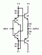
R3 & R4 aid Thermal Stability of the stage.
Take Vbe of Q1 @ 10mA ~620mV and Vbe of Q3 @ 100mA ~620mV.
Reduce R3 and R4 to 0r0.
When the input diamond is biased to 10mA the output is biased to 100mA.
Now let the input bias and/or Vbe change slightly to 10.5mA @ 618mV.
In the meantime the output has warmed up and the Vbe for 100mA has become 610mV.
The input diamond applies 618mV but the output only needs 610mV.
What happens to the excess of 8mV?
It turns on the output harder. The output bias current increases. The output transconductance determines the increase in output bias. Let's assume the output transconductance @ 100mA is 8S, i.e. 8A /V = 8mA /mV. For a 8mV cgange we would expect about 64mA of extra current to flow. The output bias has changed from 100mA to ~ 164mA. How hot do the output Tj become? How low does the Vbe become?
How high does the output bias current become?
Thanks Andrew. If I understand you correctly they are a safety measure to guard against thermal runaway resulting from mismatched transistor characteristics.
I'm still missing something. Why is the current though the output (Q3,4) 10 times larger than the current through the input drivers (Q1,2)?
The transistors are the same.
In the example, R1,2 are 5k. Say the circuit runs on bipolar 5 V supplies. The voltage drop across R1 is about 4.4 V, so Q1 (and Q2) is biased to just under 1 mA. If the Vbe for 1 mA is 0.66 V, this voltage is applied to the base of Q3 and Q4, so, with R3,4 at 0R, Q3 and Q4 also run at 1 mA, assuming they are the same model of transistor as Q1,2.
If R3,4 are 2R, the Vbe of Q3,4 is reduced by a relatively trivial 2 mV, reducing the current through Q3,4 to something slightly less than Q1,2.
My problem is if I want to run the driver and output stage at 30 mA, the resistance value of R3,4 for an equivalent Vbe drop would have to be 15 times smaller than the value listed, about 0.15 ohm, to avoid quenching the output bias current.
Alright, not a big problem: those resistors do exist, just not something I have on hand. My question though is for the case where driver and output run at the same current, how necessary are they? (The transconductance for BD135/6 I'm using appears to be about 1 S.)
Last edited:
The diagram does not state the transistors are the same.
Now set the current cold and Vbe cold for all the trannsistors and start from there as the circuit operates.
The emitter resistors are a form of feedback. Not just helping to adjust for imbalances in devices parameters but setting the stage amplifier characteristics.
Now set the current cold and Vbe cold for all the trannsistors and start from there as the circuit operates.
The emitter resistors are a form of feedback. Not just helping to adjust for imbalances in devices parameters but setting the stage amplifier characteristics.
If the transistors are the same then the resistors guarantee that the output stage runs at lower current than the input stage. I assume this is not what is intended, so probably the output stage uses bigger transistors. The resistors then help regulate the current, reduce thermal runaway, and may also smooth out the crossover region by reducing effective gm while both output transistors are contributing to the signal. R3/4=1/S would smooth the crossover, approximately.
My gut reaction is that this is a poor design, as you don't really have much control over quiescent current. It could easily be that the AC and DC requirements call for different values of the resistors, so you have to adopt a compromise. However, there could be some clever trick in it which I have missed.
My gut reaction is that this is a poor design, as you don't really have much control over quiescent current. It could easily be that the AC and DC requirements call for different values of the resistors, so you have to adopt a compromise. However, there could be some clever trick in it which I have missed.
Remember that the original design called for very low bias current, 2 mA, so all the transistors could be same without blowing the power budget. And with a low current and only 2 ohm emitter resistors, the driver and output transistor currents would be almost the same, though as you say, the output (Q3,4) will always be slightly lower than the driver (Q1,2).
As a line driver it's not an especially poor design. As a power amp ... not a good idea. I am hoping to nudge it up a little bit from line driver to headphone amp.
As a line driver it's not an especially poor design. As a power amp ... not a good idea. I am hoping to nudge it up a little bit from line driver to headphone amp.
You are correct.If the transistors are the same then the resistors guarantee that the output stage runs at lower current than the input stage. I assume this is not what is intended, so probably the output stage uses bigger transistors.
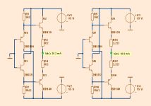
If we put bigger transistors like a TO-126 pair such as BD139,BD140,
then there is a larger effect of these emitter resistors.
See diagram.
Left has no resistance 0 Ohm, Right has 2.2 Ohm resistors.
This makes current much lower in output pair.
25mA vs 10mA
Attachments
The important characteristic that the added resistors brings to the circuit is not "lower output bias".
The far more important benefit is lower variation in output bias. This is mandatory to get the circuit working for all ambient and loading and PSU variations.
Lower output bias is a by product of stabilising the bias setting. The output bias can then be "adjusted" to whatever value one requires after the circuit has been Thermally Stabilised.
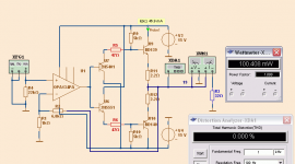
Typical use of diamond is output buffer to an opamp.
Like in my schematic.
It is a 32 Ohm headphone amplifier.
Current is set by R5,R6 (47 Ohm) and is 46mA.
This gives Class A operation 92mA.
100mWatt is very high level. Too high for ears.
Distortion is very, very low, thanks to buffer.
Like in my schematic.
It is a 32 Ohm headphone amplifier.
Current is set by R5,R6 (47 Ohm) and is 46mA.
This gives Class A operation 92mA.
100mWatt is very high level. Too high for ears.
Distortion is very, very low, thanks to buffer.
Attachments
Best article on diamond buffers, no need to re-invent the wheel:
http://waltjung.org/PDFs/WTnT_Op_Amp_Audio_2.pdf
http://waltjung.org/PDFs/WTnT_Op_Amp_Audio_2.pdf
Lower output bias is a by product of stabilising the bias setting. The output bias can then be "adjusted" to whatever value one requires after the circuit has been Thermally Stabilised.
I understand this, though exactly what "Thermally Stabilized" means in practice is still a little fuzzy. (how can you test to be certain?) I also understand that using larger transistors on the output will increase the output-to-driver current ratio.
Keeping with the basic LH0002 circuit and using the same transistors, to me it's quite acceptable to have a slightly lower output current if it means stability. A problem only develops if the price of "Thermally Stabilized" is a drastic reduction in output current.
I tried 1 Ohm and got a driver-output current ratio of about 2:1. The circuit is stable at idle, but I have not stress tested it at all. If a 0.3 Ohm emitter resistor is also stable, I'd prefer to use that, just for the sake of keeping the currents (and thus temperatures) as close as possible in the driver and output stages.
My prototype is showing a variety of problems right now, but the buffer is working as advertised at least in DC characteristics. 1 Ohm is borderline but I could live with it. I'd like to go smaller, so one of my priorities is to develop a reliable testing method for evaluating how small is too small.
Last edited:
also, the LH0002 uses monolithic devices.
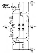
if/since you don't, i think you should add the emitter resistors to the input devices; R1 and R2 as shown in the LM6321 schematic, which is a favorite buffer of mine during the years it was available. the pointer to Walt's article was good info!
mlloyd1
if/since you don't, i think you should add the emitter resistors to the input devices; R1 and R2 as shown in the LM6321 schematic, which is a favorite buffer of mine during the years it was available. the pointer to Walt's article was good info!
mlloyd1
Why would you want to go lower ? 4.7R is low enough in your application.My prototype is showing a variety of problems right now, but the buffer is working as advertised at least in DC characteristics. 1 Ohm is borderline but I could live with it. I'd like to go smaller, so one of my priorities is to develop a reliable testing method for evaluating how small is too small.
Iddle current ? But the current through the output stage must be adjusted with resistors in the input stage, as explained by Jung, not by playing with those resistors.
Output impedance ? But a diamond buffer is best used inside a feedback loop, they're not conceived to be used open loop unless you add coupling caps or a servo. Once you take feedback into account, the output impedance will be way lower than necessary for headphones or line duty.
Last edited:
Ben,
You and I don't seem to be quite on the same page. I'm not interested in following Walt Jung's approach. It has it's merits, but it's not the only way to skin this cat.
I'm working on a heavy duty version of the four-transistor LH0002. The driver and output transistors are the same, and run at very nearly the same operating point. The driver transistors actually have a higher bias current than the output transistors, ensuring stability with increasing ambient. There are only four transistors and four resistors. The emitter resistors on the driver transistors set the driver bias and the base value of the driver current, this current is very stable owing to the large value of the emitter resistor. The emitter resistors on the output transistors are comparatively tiny, as they otherwise significantly reduce the output current from the base value. The circuit uses well matched transistors operating at very similar temperatures, and the circuit operates completely in class-A. Distortion is therefore very low, such that it should not be necessary to apply global feedback and the stability issues thereof.
That's the white paper. It may or may not work out, but you have to try something different if you want to do something different.
Last edited:
I understood all that. In my view, Jung's approach indeed has merits: it's stable, you can easily and independently set the iddle currents in the input and output stages, you can use smaller/cheaper/faster devices in the input, you get more power into the load for the same iddling current while staying in class A. All that for 4 transistors and six resistors.
I fail to see any merit in a copy of the old lh0002 compared to those advantages. But whatever floats your boat.
Btw, there should be no particular stability problems with a diamond buffer in an opamp feedback loop. It has been done many, many times.
I fail to see any merit in a copy of the old lh0002 compared to those advantages. But whatever floats your boat.
Btw, there should be no particular stability problems with a diamond buffer in an opamp feedback loop. It has been done many, many times.
- Status
- This old topic is closed. If you want to reopen this topic, contact a moderator using the "Report Post" button.
- Home
- Amplifiers
- Solid State
- Diamond Buffer Emitter Resistor Question