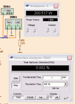
All just #'s , man ! Add TMC and that drops to .00008%. In real life , layout and parts selection (Mje350 vs. 2sa1381 , etc.) will make more impact (below). Choices of cascoding and LTP device selection are the only remaining factors as the THD is so low that noise,hum and PSRR become the only remaining considerations.
OS
OS
Attachments
Last edited:
What is one TMC, ostripper.
I have never used one. Are they expensive.
Real life.
Unfortunately I have no possibility to build anything.
I know most posters here understand this is is a careful SPICE design.
This is absolutely no secret.
Those who wants good amplifier can do so ... or not.
I have seen people build many amplifiers of more crappy quality.
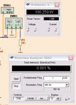
OPS is also a factor , add a triple EF or a lateral as output stage and you can refine the amp for the purpose intended. THD and the "charactor " of the resulting amp will be changed. TMC is just a "hat trick" discussed in the Cordell thread that will , in real life, allow the amp to sound "first watt" at 100 watts. 
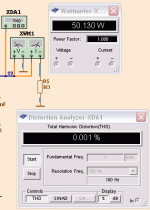
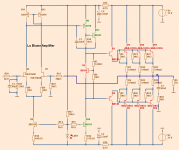
The resulting amp is pure "wire with gain" (below).. add a cascode for Jfet or super low noise IPS.
OS
The resulting amp is pure "wire with gain" (below).. add a cascode for Jfet or super low noise IPS.
OS
Attachments
Last edited:
Your OPS looks "wrong" , my example is "tried and true" (2.2R basestoppers - EF2 with 220R/10uF- driver Re/"charge suckout cap"). 3 pair is good for 4R sub use (I have one of them, too).
1k B-E resistor ???
PS - the .01R's are just to test for driver currents...
OS
1k B-E resistor ???
PS - the .01R's are just to test for driver currents...
OS
Last edited:
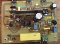
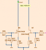
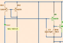
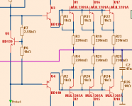
Top of input is a mirror. fig.1
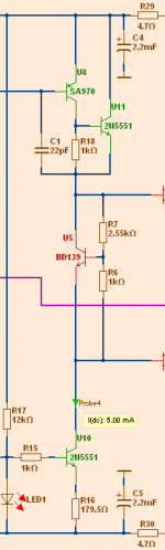
VAS are 2 transistors in complementary foldback. fig.2
VAS is biased by a current source 5 mA
VAS supply lines are filtered 4.7 Ohm 2.200uF
4.7R / 2200uF = possible turn on "thump". OPS will stabilize before VAS/IPS will.
4.7-10R /100u - 220uF will have better results.
VAS/IPS CCS's also have to be "linked" (same reference if decoupled) or "thump" will be noticable. This amp is very forgiving , but the considerations I proposed will be quite noticeable with day to day use.
Cascode the Jfets , many choices will only run 30V and under.
OS
Last edited:
What is one TMC....
Transistional Miller Compensation. It is kind of like TPC, two pole compensation, but the resistor (R19) connects to the output signal instead of GND. For TMC, at higher frequencies, the capacitor (C7) impeadance will be much lower than the resistor so it appears to the circuit as regular Miller compensation. But for lower frequencies the second capacitor's Z is higher than the resistor so the output stage is within a local compensation loop. It tends to prevent the typical frequency peak that is associated with TPC.
(ckt ref post #6)
Last edited:
- Status
- This old topic is closed. If you want to reopen this topic, contact a moderator using the "Report Post" button.
- Home
- Amplifiers
- Solid State
- LU BLAME. 200 Watt power quality. (Lineup Blameless by D.Self concept)