Hi everyone,
I have two NAD 214 amplifiers that I want to modify to augment the current-carrying capacity into a load of 4 ohms and below.
The NAD 214 is rated at 80W /8R 120W /4R.
Its bigger brother, the NAD 216 is rated at 125W /8R 200W /4R
Internally, the only difference between the two is that :
The 214 has a supply of about +/-58V and 4 output transistors per channel
The 216 has a supply of about +/-70V and 8 output transistors per channel.
The same PCB is used for both models, only not fully populated in the 214.
I was thinking of adding the 4 missing transistors per channel, while keeping the supply voltage the same. I would also double the capacitance of the power supply.
Those amplifiers will be used in a vertical bi-amp arrangement, where each amp will have one channel driving the woofer and the other channel driving the mids & tweeter.
So, my reason for coming here is to get your comments about the viability of this conversion.
The following points would need clarifying, as I am not an expert in amp design.
1--- Due to the fact that the amps will be used in a vertical bi-amp arrangement, only one woofer is being supplied by each amp, so the current load on the transformer will be halved. This would allow (theoretically) the output current capacity to be almost doubled. Correct?
2--- The transistors actually being used are the 2SC3519 / 2SA1386. As I am not sure of the resulting matching if I just add another pair to the existing one, I would prefer to replace all transistors with the excellent MJL3281A / MJL1302A. They are rated at the same 15A, but good for 260V instead of 160V, and 200W instead of 130W. Now, if I do this mod only on the channel that will be driving the woofer (while leaving the other channel unchanged), could I have a gain mismatch between the two channels because of the different hFE of the new transistors ?
3--- All transistors in the amp each have an emitter resistor of 0.2 ohms 3W, which I will be changing to new ones of 5% tolerance, but will probably be wirewound. I do know about the dangers of oscillation with fast transistors and inductive resistors, so I would like to ask for your opinions on this. I'm (wishfully) thinking that at .2 ohms, the inductance must be very low...
4--- All transistors have a “fusible” resistor of 4.7 ohms ½W in series with the base. This is a custom resistor by NAD. What is the use of this resistor? Is this a kind of fail-safe arangement that would prevent catastrophic damage in the event of a single transistor shorting out ? Does it also have an equalizing effect on the matching of all transistors ? Could I replace those with standard resistors, or would it be preferable to buy additional ones from NAD to populate the boards ?
5--- The driver transistors are the 2SC4793 / 2SA1837. Would there be any advantage in substituting them with “better” ones, like MJE15034 / MJE15035 ?
Any other mods you guys would do to this amplifier ?
Are there any things I should NOT do ?
The schematic is here
Thanks for your comments.
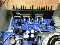
Here is a picture of the 214, right channel.
One thing that I don't like, on the 216 the heatsinks seem to be one inch higher. I might be a bit short on area with these ones...
Anyone owning a 216 can confirm that your heatsinks come close to the top cover ?
Thanks
One thing that I don't like, on the 216 the heatsinks seem to be one inch higher. I might be a bit short on area with these ones...
Anyone owning a 216 can confirm that your heatsinks come close to the top cover ?
Thanks
Attachments
Adding more output transistors should be a straightforward drop in, if you use the same type transistors. If you substitute different ones, the circuit may well become unstable due to the different characteristics of the output transistors.
The 2SC4793/2SA1837 are excellent driver transistors, so no need to change them.
Try and find some metal oxide based emitter resistors. Wirewounds should be OK though.
The larger heatsink on the 216 would be because this design has a higher supply voltage, so extra heat to dissipate.
Overall, what you are looking for is an increase in the current delivered. The limiting factor here is the VA of the transformer. Adding more capacitance won't really help much with this, as it will still be limited by the available current from the transformer.
A big thank you, jaycee for your comments.
Yes indeed, the 216 has a higher supply voltage, hence more dissipation. To compensate, NAD idles the transistors at 40mA in the 216, instead of 45mA in the 214. And they added heatsink area.
About adding capacitance, it's just because there is space on the board for 6x 6800uF, and presently there are 4x 4700uF.
As the amp will be driving only one speaker enclosure instead of two, the load on the transformer will be reduced and allow me to get more power into low impedances, I assume.
Pardon me for hijacking this thread, but I have a NAD 214 in need of new 125 V 7A glass fuses and can't find any information to answer what type they are when ordering (typical types are slow blow, fast blow, electronic, etc) and I know nada. (bought it used, first attempt to get operational)
- Status
- This old topic is closed. If you want to reopen this topic, contact a moderator using the "Report Post" button.
- Home
- Amplifiers
- Solid State
- Modifying the NAD 214