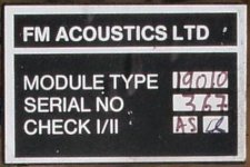
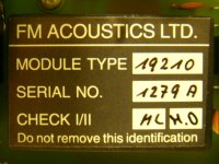
I would be willing to bet if you broke it open you would find standard transistors, maybe with their numbers removed or faces glued together to control temp matching. It's in a module box with epoxy filling for a reason. Huber just uses a lot of attention to detail; matching every part and burning every part in before the circuit is assembled. I would also bet that the circuit is not that new or earth shattering but rather standard circuit design known from the late 60s. Ray
Hylle:
I drew that schematic - reverse engineered from pictures of both sides af the PCB found on the www.
I have no values or transistor-types for it.
(The 10uH value is a mistake - when drawing the schematic in Pspice I must have used this value for the last coil I used, and then I forgot to erase it)
I guess the coils will prohibit HF oscillations in the output transistors.
Please use the schematic as inspiration only, and to study the circuit topology.
It seems to be simple and proven technology ( and for that age maybe even quite modern), but with focus on component quality.
Hylle:
The 10uH value is a mistake - when drawing the schematic in Pspice I must have used this value for the last coil I used, and then I forgot to erase it.
I guess the coils will prohibit HF oscillations in the output transistors.
Thanks for clarifying this, very helpful.
Hylle:
I drew that schematic - reverse engineered from pictures of both sides af the PCB found on the www.
I have no values or transistor-types for it.
(The 10uH value is a mistake - when drawing the schematic in Pspice I must have used this value for the last coil I used, and then I forgot to erase it)
I guess the coils will prohibit HF oscillations in the output transistors.
Please use the schematic as inspiration only, and to study the circuit topology.
It seems to be simple and proven technology ( and for that age maybe even quite modern), but with focus on component quality.
Thank you for schematics. Does this schematic belong to the Classic or the Resolution series?
Links below has details to some amps and preamps.
Home / Fm-Acoustics / Power-Amplifiers | HIFI SHOCK
Home / Fm-Acoustics / Preamplifiers | HIFI SHOCK
...however I did some shortcuts: there are two pairs of output resistors, and the "R4" is ofcourse a standard thermal regulator circuit.
So please use only this drawing to study the circuit.
if you want to go further, then here is what I redraw (warning 6Mb file download):
...the picture from the topside of the PCB in the monoblocks.
You might be able to spot some resistorvalues and read the small signal transistors also. However if FM acoustics really are doing the extreme selection of transistors as they mention, and specify their own output transistors, then I think it would be a bit hard to clone.
Besides you might want to choose some other transistors anyway, since the originals probably are obsolete, and judging by the cooling fins they might be a bit hard pushed in this circuit.
Found this video on youtube, very detailed sound.
Tamacun ? Rodrigo Y Gabriela - Live in Japan 2008 - YouTube
and
YESTERDAY ? Beatles - YouTube
Tamacun ? Rodrigo Y Gabriela - Live in Japan 2008 - YouTube
and
YESTERDAY ? Beatles - YouTube
- Status
- This old topic is closed. If you want to reopen this topic, contact a moderator using the "Report Post" button.
- Home
- Amplifiers
- Solid State
- fm acoustics

