Hello Les, I can't speak from experience on this particular design, but in general, if you have no capacitors in the signal path it reduces distortion. This is because capacitors (and all other components) have some degree of nonlinearity. This nonlinearity is what introduces the distortion. The ultimate goal of an amplifier designer/builder is the "straight wire with gain". That is the goal that still eludes all of the amps out there. Admittedly, there are some that are very close, but nothing is perfect.
Peace,
Dave
Peace,
Dave
Positives
1. It's simple.
2. It's straightforward to build and set up.
3. There are no transformers (except the one in the PSU).
4. There are no caps in the signal path.
5. It has a usefully high input impedance.
5. Response goes down to DC, up to RF
Negatives
1. Response goes down to DC, up to RF
2. There are no transformers (or caps in the signal path), so
3. It will take a small DC input and drive a large current through your speakers, destroying them, if you don't take measures to prevent it. The obvious measure is to have a series capacitor in the source, which is what you were trying to avoid. Ho hum. You'll still get DC offset, so you might want a cap at the output...
4. It wastes a lot of power.
5. It takes ~1 hour to warm up.
w
3. It will take a small DC input and drive a large current through your speakers, destroying them, if you don't take measures to prevent it. The obvious measure is to have a series capacitor in the source, which is what you were trying to avoid. Ho hum. You'll still get DC offset, so you might want a cap at the output...
That's the question.. is the lack of phase shift or simplicity worth the risk of a catastrophic meltdown ?
Whether it is "good" or not is not the issue. IS IT WORTH IT ?? Most of the class AB's at DIYA will run input capacitor-less (it's not a stability issue) ... some actually do with a DC servo. Even those servo amps recommend minimal DC offset at the source. The source , preamp , and anything else upstream will have varying degree's of phase shift to begin with .... so it is anal to worry about it at the input of the main amp
 .The only exception would be with Bi or tri -amped active setups.There , you would just use the same amp (topology) for all.
OS
To me it sounds like that folks who are in the Solid State forum most of the time are not very familiar with the Pass Labs forum and that is natural.
The comments about no caps in the amp stage of the F5 refers to the absence of any type/value of decoupling caps for the power rails. As to why it is so, I don't recall having seen any convincing reason and Nelson also has not told us why? I posed the question myself, as I am designing my own PCB for a modified F5 and have not heard anything concrete.
So now you can comment on the pros/cons of using/not using decoupling caps on the amp board, when you have separate PSU board and PSU cables.
No caps ??
Hmmm ???

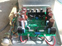
Working on just these things... so that's the ??? Nothing wrong with the main caps on the OPS PCB , just run a separate return to star.... eliminates the inductance of the wire but complicates board/ chassis layout. Separate PS boards w/ wires can be coaxed to behave as well , just (properly) decouple at the power board rails. Leach explains about the high Q circuit formed between a length of wire + the normal .1uF rail cap , he eliminates the issue with a 10-100uF. The F5 will amplify VHF , so that high Q might be more of a issue.
wow ! that's a nice CRC PS .
OS
To me it sounds like that folks who are in the Solid State forum most of the time are not very familiar with the Pass Labs forum and that is natural.
The comments about no caps in the amp stage of the F5 refers to the absence of any type/value of decoupling caps for the power rails. As to why it is so, I don't recall having seen any convincing reason and Nelson also has not told us why? I posed the question myself, as I am designing my own PCB for a modified F5 and have not heard anything concrete.
So now you can comment on the pros/cons of using/not using decoupling caps on the amp board, when you have separate PSU board and PSU cables.
Hmmm ???
Working on just these things... so that's the ??? Nothing wrong with the main caps on the OPS PCB , just run a separate return to star.... eliminates the inductance of the wire but complicates board/ chassis layout. Separate PS boards w/ wires can be coaxed to behave as well , just (properly) decouple at the power board rails. Leach explains about the high Q circuit formed between a length of wire + the normal .1uF rail cap , he eliminates the issue with a 10-100uF. The F5 will amplify VHF , so that high Q might be more of a issue.
wow ! that's a nice CRC PS
.OS
Working on just these things... so that's the ??? Nothing wrong with the main caps on the OPS PCB , just run a separate return to star.... eliminates the inductance of the wire but complicates board/ chassis layout.
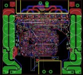
I agree with this. PS caps should be somewhat near the load for them, that being the output stage. I have discovered that it is worth the extra effort to design the PS and the amp on the same PCB, such as in this one. You have to be aware of the high current return paths so they will not cause interference. Although since this amp OPS is a full bridge, there is no speaker return to GND.
...and the next updated version (in process) still a bunch of work yet, hope to finish it soon.
Attachments

- Status
- This old topic is closed. If you want to reopen this topic, contact a moderator using the "Report Post" button.
- Home
- Amplifiers
- Solid State
- F5 no caps in amp stage,,,why is it good?