...is something I've already done.
Ah, but I >need< another one. It will be the new driving force for my main speakers which are 3-way active. Basically it's taking the place of the 'old' 6 channel and and the old gets upgraded and reused for 2 other 2-way speakers (centre, rear surrounds of an HT experience).
So, some basic details: the new one will be in the same style as the original, same outward appearance with a few cosmetic changes. It will be slightly bigger, to accommodate larger heatsinks and more powerful amplifiers. It will be more sophisticated, especially the power supply.
End of preface.
")
Ah, but I >need< another one. It will be the new driving force for my main speakers which are 3-way active. Basically it's taking the place of the 'old' 6 channel and and the old gets upgraded and reused for 2 other 2-way speakers (centre, rear surrounds of an HT experience).
So, some basic details: the new one will be in the same style as the original, same outward appearance with a few cosmetic changes. It will be slightly bigger, to accommodate larger heatsinks and more powerful amplifiers. It will be more sophisticated, especially the power supply.
End of preface.
The most important thing about any amplifier, regardless of the complexity, is how it looks. That is actually the easiest part for me, usually - the things I make (that actually get finished) look good. Or at least they do to me.
With that important info out of the way, we are free to look at the other minor details that make up a project such as this, starting with the individual amp modules themselves. For this project, I've dusted off a design I ripped off a couple years ago - the Abomination, I called it. It is a folded cascode that closely resembles the Luxman M-02 (and some more recent (or prior?) variations).
I made some changes to it, mainly to operating points and the compensation scheme. I changed cdom from a shunt type compensation to a miller type. This, according to reliable info and verified by simulation, lowers HF distortion.
The schematic:

and in pdf for those who wanna closer look: View attachment EMBER.pdf
With the changes, I changed the name to Ember. The reason for that will be more apparent when I show the finished amp.
That is actually the easiest part for me, usually - the things I make (that actually get finished) look good. Or at least they do to me.With that important info out of the way, we are free to look at the other minor details that make up a project such as this, starting with the individual amp modules themselves. For this project, I've dusted off a design I ripped off a couple years ago - the Abomination, I called it. It is a folded cascode that closely resembles the Luxman M-02 (and some more recent (or prior?) variations).
I made some changes to it, mainly to operating points and the compensation scheme. I changed cdom from a shunt type compensation to a miller type. This, according to reliable info and verified by simulation, lowers HF distortion.
The schematic:
and in pdf for those who wanna closer look: View attachment EMBER.pdf
With the changes, I changed the name to Ember. The reason for that will be more apparent when I show the finished amp.
Last edited:


Getting 6 of these amp modules to fit on the heatsinks I've procured required a tight layout. My heatsinks are 4 pieces, 8" high x 8.5" wide. That would be 2 per side, making the sides (and total heatsink area) 8" x 17".
The amps will mount directly onto the heatsinks, freeing up needed space inside the chassis. This also results in better heat transfer.
The layout:

and assembled:

a look at the undercarriage:

The amps will mount directly onto the heatsinks, freeing up needed space inside the chassis. This also results in better heat transfer.
The layout:
and assembled:
a look at the undercarriage:
This looks very good! Nice compact design using Thermaltrak devices. Is that schematic your final, final version?
Thanks and yes, the schematic is final, final (at least the pdf one is, R17 on the screen pic is 22R, should be 33R).
Even though I had a working prototype:

I made enough changes to the layout to warrant testing the new one:

That's running on +/-55V rails on the output stage, +/-56V regulated cap multiplier supply for the front end. Working splendidly.
1K clipping into an 8 ohm load:

10K clipping:

Slight sticking but not a big concern.
With this supply, I have ~136watts into 8 ohms before clipping. The projected output is 150 watts into 8 ohms with the higher voltage supply. This higher voltage leaves some headroom to avoid clipping altogether.
Thanks and yes, the schematic is final, final
Welllll, I guess I spoke too soon.
R2 needs to be changed from 18K to 82K (just a small increase
) - there isn't any reason to pump ~7mA through the LEDs and at that current, R2 would be dissipating nearly a watt.Nice , they are starting to look more like mine ...
Really , you are "top gun" in layout.
Just a little story , lady in the Bronx bought her audiophile amp in '91. She grew up with it , throwing block parties with it until 2010. 5 years ago she said it started humming , this Christmas it finally blew up. I bought the carcass for $20.
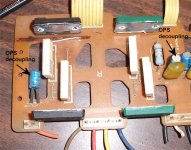
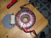
(below 1) I must admire a output stage that can survive abuse like that for 19 years (unfiltered DC for 5 years). This amp in the story (nikko alpha 230) also has the split supply like yours and mine. after reading this : Leach Amp Power Supply I realized that the standard .1uf decoupling was ill conceived , especially with X length of wire between the PS and the OPS. This L/C combo creates a High-Q resonator , A larger C (10-100uF) eliminates this .. the .1uF does nothing except possibly create a new problem. The nikko in the photo adheres to this observation closely with 2- 10uF's decoupled to chassis ground/HS (just another return path). The higher voltage input stage supply has a smaller current swing allowing a .1uF there to improve HF ESR as it was intended. Another observation is that the HV supply's decoupling(the 2 -1kuf's and the 2- .1uf's) had a separate return to the main star. In total , that is 3 return paths back to the main star (input stage , HV/zobel , and local OPS). I brought this up because this amp has one of the lowest noise /hum ratings I have seen as well as being ultra durable. Your amp , with it's 6 channels , might have some long rail feeds which could be tamed by this technique. You also might want to put the toroid in a metal box/shielding ... it throws out quite the field. It was originally potted in a metal box.
Good luck on your monster.
OS
Really , you are "top gun" in layout.
Just a little story , lady in the Bronx bought her audiophile amp in '91. She grew up with it , throwing block parties with it until 2010. 5 years ago she said it started humming , this Christmas it finally blew up. I bought the carcass for $20.
(below 1) I must admire a output stage that can survive abuse like that for 19 years (unfiltered DC for 5 years). This amp in the story (nikko alpha 230) also has the split supply like yours and mine. after reading this : Leach Amp Power Supply I realized that the standard .1uf decoupling was ill conceived , especially with X length of wire between the PS and the OPS. This L/C combo creates a High-Q resonator , A larger C (10-100uF) eliminates this .. the .1uF does nothing except possibly create a new problem. The nikko in the photo adheres to this observation closely with 2- 10uF's decoupled to chassis ground/HS (just another return path). The higher voltage input stage supply has a smaller current swing allowing a .1uF there to improve HF ESR as it was intended. Another observation is that the HV supply's decoupling(the 2 -1kuf's and the 2- .1uf's) had a separate return to the main star. In total , that is 3 return paths back to the main star (input stage , HV/zobel , and local OPS). I brought this up because this amp has one of the lowest noise /hum ratings I have seen as well as being ultra durable. Your amp , with it's 6 channels , might have some long rail feeds which could be tamed by this technique. You also might want to put the toroid in a metal box/shielding ... it throws out quite the field. It was originally potted in a metal box.
Good luck on your monster.
OS
Attachments
Thanks OS,
Your link to the Leach info is broken - did you mean this: Leach Amp Power Supply ? There it is pointed out that 100nF on it's own is too small and can cause the oscillation you mention.
I've actually given a lot of thought to the grounding scheme and abandoned my original plan to have separate ground paths from the front end decoupling, output stage decoupling/zobel. The frontend decoupling sees no high current swings and is 'upstream' from the output stage decoupling on the board. The Zobel only conducts when there is oscillation, therefore it's return path is trivial.
I welcome any and all suggestions, but like my opening line of this thread says, I've already done this and can draw upon (and improve) the lessons learned in that first build. By some stroke of good luck I managed to get the grounding in the first one nearly perfect - very silent, only limited by the lessor PSRR of the Patchwork amps.
As I work my way through this project, I'll be posting all of the detail and showing what works and what doesn't
Onwards!
I replaced R2 with 82K and have been doing some more testing, in particular thermal stability.
But first I did a capacitive load test, with a 1uF cap parallel with the 8 ohm dummy load:

The 20K squarewave with this load:

I'll take it!
Next, I've been running thermal stability tests. The setup:

My concern was where I want to mount these modules on the heatsinks (lower part) and how much of a difference there would be in temp across the heatsink.
I set Iq to ~70mA/output and let that cook for about 20 minutes. The bias drifted up slightly - 1-2mV across the 150 mohm resistor. Not a concern. I measured the heatsink temp at that time and found it uniformly warm, 1 degree in the difference between hottest and coldest.
I then gave it signal to give an output of about 10 watts into the 8 ohm dummy. Let that sit for ~15 minutes and then measured the temps. At the face of each output I measured 48*C, directly behind between the heatsink fins I got 52*C. The top corner, opposite to where the amp is mounted measured 48*C. On a sidenote, the small heatsink for the VAS measured 44*C at its centre. Q8, without a heatsink measured 41*C.
After leaving it to cool for 20 minutes, Iq remains steady at the earlier setting.
My conclusion is that having the amp mounted lower on the heatsink is acceptable, given the small variation in temp across its surface. One thing I am concerned about is whether 2 of these heatsinks are adequate for cooling 3 of these amps. The testing setup is far from ideal, as the heatsink sits on the plywood shelf, it's not as open to the air as it will be.
I may need to bolster the cooling potential by using aluminum for the sub-chassis, rather than steel, as I originally planned.
I replaced R2 with 82K and have been doing some more testing, in particular thermal stability.
But first I did a capacitive load test, with a 1uF cap parallel with the 8 ohm dummy load:
The 20K squarewave with this load:
I'll take it!
Next, I've been running thermal stability tests. The setup:
My concern was where I want to mount these modules on the heatsinks (lower part) and how much of a difference there would be in temp across the heatsink.
I set Iq to ~70mA/output and let that cook for about 20 minutes. The bias drifted up slightly - 1-2mV across the 150 mohm resistor. Not a concern. I measured the heatsink temp at that time and found it uniformly warm, 1 degree in the difference between hottest and coldest.
I then gave it signal to give an output of about 10 watts into the 8 ohm dummy. Let that sit for ~15 minutes and then measured the temps. At the face of each output I measured 48*C, directly behind between the heatsink fins I got 52*C. The top corner, opposite to where the amp is mounted measured 48*C. On a sidenote, the small heatsink for the VAS measured 44*C at its centre. Q8, without a heatsink measured 41*C.
After leaving it to cool for 20 minutes, Iq remains steady at the earlier setting.
My conclusion is that having the amp mounted lower on the heatsink is acceptable, given the small variation in temp across its surface. One thing I am concerned about is whether 2 of these heatsinks are adequate for cooling 3 of these amps. The testing setup is far from ideal, as the heatsink sits on the plywood shelf, it's not as open to the air as it will be.
I may need to bolster the cooling potential by using aluminum for the sub-chassis, rather than steel, as I originally planned.
Last edited:
after reading this : Leach Amp Power Supply I realized that the standard .1uf decoupling was ill conceived
the .1uF does nothing except possibly create a new problem. The nikko in the photo adheres to this observation closely with 2- 10uF's decoupled to chassis ground/HS (just another return path).
OS
Very illuminating, total output board bypass consisting of only 2 small electrolytics. This certainly conflicts with the " common sense "
in other posts.
I see that Eva covered this issue in a more rigorous manner with some
very nice graphics and explanation.
I would like to know if the location of these bypass caps on the power
bus is of issue. From looking at the Nikko board, they did not place them
at the entry to the board.
Specifically , they decoupled 2 of the 10uF's to the HS ground and 2 to the zobel/HV supply ground return. The caps were in the middle of the rail busses.
They especially kept the driver/VS/input ground separate from everything else. This is actually anal , as john's amp and mine are already -100db regardless of grounding .. I just thought it was interesting how a room full of Japanese audio engineers approached this issue.
OS
The Luxman M-02 has the same - 10uf decoupling on the output stage with 100nF to chassis. The Zobel is tied into this ground as well.
The front supply decoupling ground returns to that supply, which makes sense, since it is a totally separate supply.
For this one, using that big transformer you're sending me ( ), I won't be using a separate transformer for the front end supply. All power and decoupling will return to the main power star ground.
As for my decoupling, I've been doing it that way since I started. I learned it from ESP and Self and I can't find any reason to do it any other way. Output stage gets 220uF plus 100nF, frontend gets 220uF only.
The front supply decoupling ground returns to that supply, which makes sense, since it is a totally separate supply.
For this one, using that big transformer you're sending me (
), I won't be using a separate transformer for the front end supply. All power and decoupling will return to the main power star ground.As for my decoupling, I've been doing it that way since I started. I learned it from ESP and Self and I can't find any reason to do it any other way. Output stage gets 220uF plus 100nF, frontend gets 220uF only.
Howdy jaycee,
The plan, as of right now is for 1 transformer, 2 main supplies, 2 front end supplies.
The main supplies will have 100nF bypass and 39,000uF smoothing caps per rail.
The front end supplies will be regulated cap multipliers, fed from the main supplies.
Each supply will feed 3 channels - 3 left and 3 right.
Last edited:
Some chassis work today. Following my own recommendation to add more heatsink area, I cut this piece for the back:

This is 7.25" wide and cut to 18" long. The fins are only 1/2" long and tightly spaced but ever little bit helps, as far as cooling goes.
Some machining:


These recesses are for screw to fasten it to the ends of the main heatsinks. Drilled with a 3/4" forstner bit.
This is 7.25" wide and cut to 18" long. The fins are only 1/2" long and tightly spaced but ever little bit helps, as far as cooling goes.
Some machining:
These recesses are for screw to fasten it to the ends of the main heatsinks. Drilled with a 3/4" forstner bit.
I need recesses in the fins for the input jacks and the output banana jacks. I made a pair of templates:

to guide the follower bit in the router. The small template is for the input jack recess, the larger one for the outputs and the IEC and power switch.
Routed:

patience and hearing protection required! It takes several passes to cut away all of the fin. Having the template clamped down tight is critical.
The larger recesses don't go full depth:

just deep enough to make it possible to mount the jacks.
It's starting to look like something now:

temporarily attached to get accurate measurements of the other parts needed. Jacks installed for dramatic effect.
PS: no, that's not blood on the plank. Red paint.
to guide the follower bit in the router. The small template is for the input jack recess, the larger one for the outputs and the IEC and power switch.
Routed:
patience and hearing protection required! It takes several passes to cut away all of the fin. Having the template clamped down tight is critical.
The larger recesses don't go full depth:
just deep enough to make it possible to mount the jacks.
It's starting to look like something now:
temporarily attached to get accurate measurements of the other parts needed. Jacks installed for dramatic effect.
PS: no, that's not blood on the plank. Red paint.
Last edited:
Now here's where you really make me jealous. You have a tool shop and you know how to use it !
The best case I've got for an amp right now, is the guts of an old Teac A919 I got from Freecycle. Should be nice to build a 100W/ch amp into, but the original transformer is stupidly overvoltage for this (especially as it only had 1 pair of outputs!), and there's only 115mm where the transformer is for a toroid, so only ~250VA would fit.
The best case I've got for an amp right now, is the guts of an old Teac A919 I got from Freecycle. Should be nice to build a 100W/ch amp into, but the original transformer is stupidly overvoltage for this (especially as it only had 1 pair of outputs!), and there's only 115mm where the transformer is for a toroid, so only ~250VA would fit.
- Status
- This old topic is closed. If you want to reopen this topic, contact a moderator using the "Report Post" button.
- Home
- Amplifiers
- Solid State
- ☠ Building a 6 channel amplifier