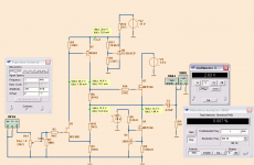
One IRFP240 for constant current
The other IRFP240 controlled by JFET feedback
True hifi and Class A
Limit just below 8 Watt into 8 Ohm
Need one jfet BF245B for correct operation (2N4416 can be used)
and one TL431 for 30 volt regulation
The other IRFP240 controlled by JFET feedback
True hifi and Class A
Limit just below 8 Watt into 8 Ohm
Need one jfet BF245B for correct operation (2N4416 can be used)
and one TL431 for 30 volt regulation
Attachments
Last edited:
Good way to Schade U3 JFET into triode emulation.
Excepting: Schade feedback to source isn't entirely DC coupled as it appears.
Some of it gets squirreled up and delayed into into M2's Miller.
I've played with that before, where U3 was an actual Triode. Mu 100, and R11/R3=100
to make a concertina splitter of equal impedance with +Mu/2 -Mu/2 gains. If you drive
two loads of similar capacitance, the pole and zero cancel. Feedback to U3's source
is not so shifted... You need equal plate and cathode or source and drain voltage type
feedbacks, I'm not sure you can arrange both at the same time with just JFET + PNP.
If you could increase impedance into that MOSFET gate somehow? U3 would behave
much more like a properly emulated triode.
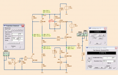
This was the phase splitter I was talkin about. Same topology as yours
except there are voltage feedbacks of equal influence at both collector
and emitter (plate Mu is feeding back the emitter) of the PNP transistor.
Anyways, if this split was driving MOSFETs of equal Miller capacitance,
one would be a Pole, and the other would be a Zero. Phase shifts would
cancel each other out, and no phase shift seen by local feedback loop.
Useful tactic, I don't know??? Does the impedance top and bottom have
to match for driven Millers to cancel? Again, I don't know...
After I closed global feedback around whole amp, the impedance match
here was forced equal anyway. I went to a lot of trouble for nothing...
You might just be able to stick a small resistor up top, and a cap equal
to your MOSFET's Miller to B+ or GND... I forget, what was I doing again?
I need to take up hard drinking, so I'll have an excuse next time...
Attachments
Last edited:
and one TL431 for 30 volt regulation
Hi Lineup!
There are many opinions that TL431 causes the oscillations,
please consider using simply 30V zener diode and FE...
Hello.Hi Lineup!
There are many opinions that TL431 causes the oscillations,
please consider using simply 30V zener diode and FE...
According to datasheet TL431 has an aera of capacitance
where it is not stable.
This can avoid by chose correct bypass capacitance.
THis is not a problem not to use TL431
I added a cap to TL431.
This keeps 30V guaranted stable.
")
with dz you will get ghostly quiet voltage source..
How about adding TCM compensation across R11?
- Status
- This old topic is closed. If you want to reopen this topic, contact a moderator using the "Report Post" button.
- Home
- Amplifiers
- Solid State
- Quick Dirty Blameless HIFI IRFP240 Class A