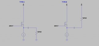
Hello All,
Please see attached figure below. We have here two configurations of a source follower amplifer running in Class A with a CCS load.
The configuration on the right passes all current drawn from the power supply through a CCS, meaning the current draw is constant. There is no direct route from the PS through the speaker to ground. It has to go through the CCS first (thanks AndrewT).
The configuration on the left is free to pass whatever it can through the load.
So, what are the pros and cons of each configuration?? Clearly a constant current draw will make things easier on the power supply and probably cause less supply induced noise. However, will the constant current version be able to supply enough current to supply the speaker adequately and provide good extension at low frequencies or when the impedance drops? Might this reduce bass where one assumes the more current the better?
Any thoughts on the relative merits of each configuration would be appreciated.
Regards,
Greg.
Attachments

I reminds me Ciuffioli's mosfet follower, it uses a capacitive multiplier power supply. I call it a shunt amplifier.
Did you eventually come to some conclusions about merits of the shunt amp?
I remember that article can you post the rest if it or email it to me please?
I have been doing some designing in circuit maker on class a power amps lately. jer
Hi, you'll find it here :
Andrea Ciuffoli - Documentation page
Agree with Swordfishy.
The currents through the mosfet and the speaker are conjugate; they always add to a constant, the current which passes through the CCS. And because the speaker is referenced to the positive rail (ground) and the CCS has very high impedance in the megohms to the negative rail, there is almost no hum at all despite modest filtering.
This approach marginally reduces dissipation in the source follower, too, giving symmetrical currents through it which inverse track speaker currents.
I did an amp like this some years ago, SE mosfet with large CCS, but adopted the usual power supply approach. I had to use 2 x 22,000uF, a 15mH 3A choke, and still I can hear some hum. This approach is much smarter, hats off to Andrea, who is now 44 and into his prime.
Ciao,
Hugh
forr,
For what reason if may ask?I call it a shunt amplifier.
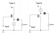
Hello All,
Please see attached figure below. We have here two configurations of a source follower amplifer running in Class A with a CCS load.
The configuration on the right passes all current drawn from the power supply through a CCS, meaning the current draw is constant. There is no direct route from the PS through the speaker to ground. It has to go through the CCS first (thanks AndrewT).
The configuration on the left is free to pass whatever it can through the load.
So, what are the pros and cons of each configuration?? Clearly a constant current draw will make things easier on the power supply and probably cause less supply induced noise. However, will the constant current version be able to supply enough current to supply the speaker adequately and provide good extension at low frequencies or when the impedance drops? Might this reduce bass where one assumes the more current the better?
Any thoughts on the relative merits of each configuration would be appreciated.
Regards,
Greg.
In the left circuit, the 'infinite current' that can be passed to the load is only in one phase of the signal; the other phase still has to go through the CCS. In that aspect, the V RMS output capabiliites of the two circuits are identical.
jan didden
forr,
For what reason if may ask?
Do you mean availability of ground for such a term (shunt amplifier) in textbooks ?
VladimirK,
what is the meaning of the "shunt concept" and who introduced it?
Saying that, one has in mind definite design approach, published by Andrea Ciuffolli, maybe somebody else employed it before him without publication (one never sure). As for specific term denoting such design approach, its a question of mutual agreement. one could propose, for instance, "Ciuffolli's Follower" term, instead of the "shunt concept". Of course, if such approach has been already determined in a textbook, then one must inform community about it and then would be correct to use an established term.
forr,
For what reason if may ask?
If you replace the top left Mosfet of Ciuffoli's circuit by a zener (supposing it could dissipate a lot of power), you'll have a DC, parallel, shunt regulator. Don't you think that with the Mosfet driven by an AC voltage there is some ressemblance with the zener circuit ? The load is parallel with what could be considered as an AC regulator.
Hi forr,
Ciuffoli is making erroneous suppositions without explaining the "concept" clearly. On the other hand, there´s nothing to explain, the whole thing reminds me of the Emperor's new clothes.
It is a common drain amplifier, also called source follower or unity gain voltage buffer. As far as AC is concerned, the drain and source side rails are united by the power supply capacitor serving as signal ground, however, a reference to the drain side gives improper biasing. The amplifier does not give a damn about what is designated positive, negative and zero volt.
Hi forr,
Ciuffoli is making erroneous suppositions without explaining the "concept" clearly. On the other hand, there´s nothing to explain, the whole thing reminds me of the Emperor's new clothes.
It is a common drain amplifier, also called source follower or unity gain voltage buffer. As far as AC is concerned, the drain and source side rails are united by the power supply capacitor serving as signal ground, however, a reference to the drain side gives improper biasing. The amplifier does not give a damn about what is designated positive, negative and zero volt.
As much as I hate to admit it,
") I must agree with you completely. There's no conceptual difference between the two circuits.
I must agree with you completely. There's no conceptual difference between the two circuits.jan didden
- Status
- This old topic is closed. If you want to reopen this topic, contact a moderator using the "Report Post" button.
- Home
- Amplifiers
- Solid State
- Constant Current Pros and Cons