First off - I am a newbie to solid state amps.
My friends Basic Black bass amp has a cooked power transformer.
We were playing a gig and we could smell something burning and it blew the fuse.
Little did I know, he had it plugged into a 2 ohm cabinet!
I took it home and put in a new fuse and it promtly blew the internal fuse.
I check the resistance in the primary and it is about 1.4 ohms.
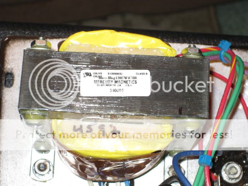
The red wires on the output (91 v) look like they overheated.
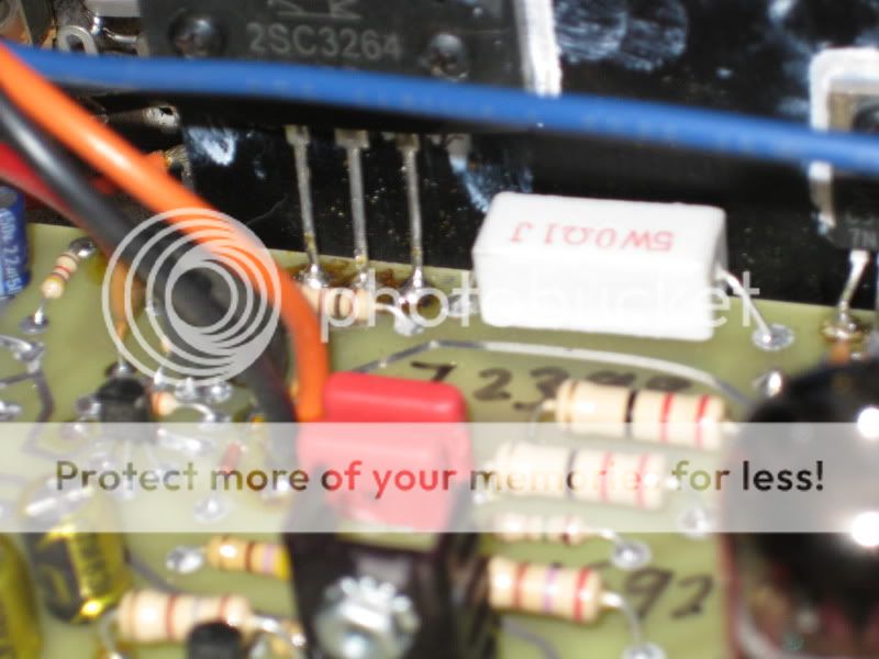
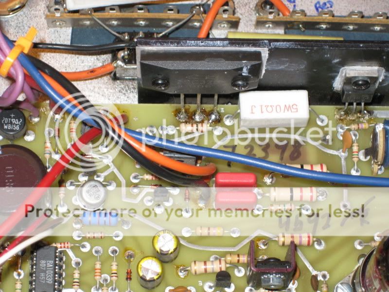
The areas of the board where the transformer wires are attached and around the output transistors are attached look like they got hot.
The transistors themselves LOOK ok.
My question is; can the PT get fried from overload and the rest of the components survive?
I can't seem to find a schematic that includes the power supply section.
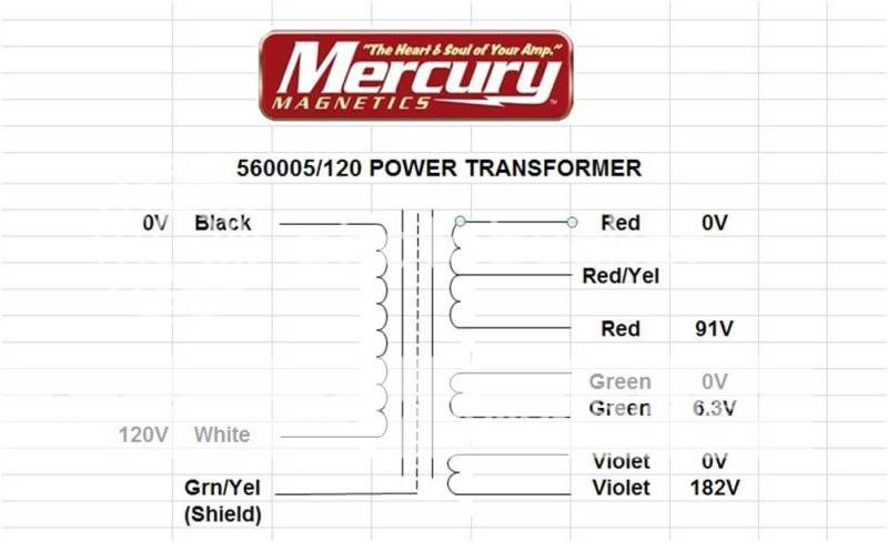
The PT is a Mercury Magnetics 560005.
I called them and they are $150 and they would need to wind one since they don't have them in stock.
The spec sheet they sent me says the PT has one primary but the actual transformer has 3. a blue set of wires is not used, and the primary wires used are actually two sets of black and white (one set has a stripe).
Does anyone know where to get a generic transformer?
My friends Basic Black bass amp has a cooked power transformer.
We were playing a gig and we could smell something burning and it blew the fuse.
Little did I know, he had it plugged into a 2 ohm cabinet!
I took it home and put in a new fuse and it promtly blew the internal fuse.
I check the resistance in the primary and it is about 1.4 ohms.
The red wires on the output (91 v) look like they overheated.
The areas of the board where the transformer wires are attached and around the output transistors are attached look like they got hot.
The transistors themselves LOOK ok.
My question is; can the PT get fried from overload and the rest of the components survive?
I can't seem to find a schematic that includes the power supply section.
The PT is a Mercury Magnetics 560005.
I called them and they are $150 and they would need to wind one since they don't have them in stock.
The spec sheet they sent me says the PT has one primary but the actual transformer has 3. a blue set of wires is not used, and the primary wires used are actually two sets of black and white (one set has a stripe).
Does anyone know where to get a generic transformer?
you must first check the diodes and especialy the output devices first.
Otherwise you will be replacing another transformer.
First disconnect the transformer from the rest of the circuit to verify if indeed the transformer is actualy blown.
I have seen some survive in such a case. jer
p.s. even if they look okay they very well may be shorted.
Otherwise you will be replacing another transformer.
First disconnect the transformer from the rest of the circuit to verify if indeed the transformer is actualy blown.
I have seen some survive in such a case. jer
p.s. even if they look okay they very well may be shorted.
Last edited:
also if you can find out what the voltage and power rating of the transformer .
I'm sure one could find a suitable replacement for alot less.
I did the same thing to my ampeg V4-B ( sad) and cooked the output transformer but there is no way around that one.
$200 + for a new one and just as much (if not more) to have it rewound. jer
I'm sure one could find a suitable replacement for alot less.
I did the same thing to my ampeg V4-B ( sad) and cooked the output transformer but there is no way around that one.
$200 + for a new one and just as much (if not more) to have it rewound. jer
Last edited:
Stevie B. Nice photos, well done, but please see this thread.
http://www.diyaudio.com/forums/everything-else/183084-pictures-why-not-attach-them.html
http://www.diyaudio.com/forums/everything-else/183084-pictures-why-not-attach-them.html
Sorry if I have missed it somewhere but the first quick check has to be across the output transistors and across the rectifier.
Disconnect the secondaries and power the tranny up if in doubt.
A large power transformer will have a very low DC resistance across the primary... that's normal, and at AC the "impedance" is far higher.
Disconnect the secondaries and power the tranny up if in doubt.
A large power transformer will have a very low DC resistance across the primary... that's normal, and at AC the "impedance" is far higher.
3 primaries is probably to implement 120/220/240V input.
If you wire these primaries out of phase it will draw a lot of current. This does not necessarily mean the transformer is shorted.
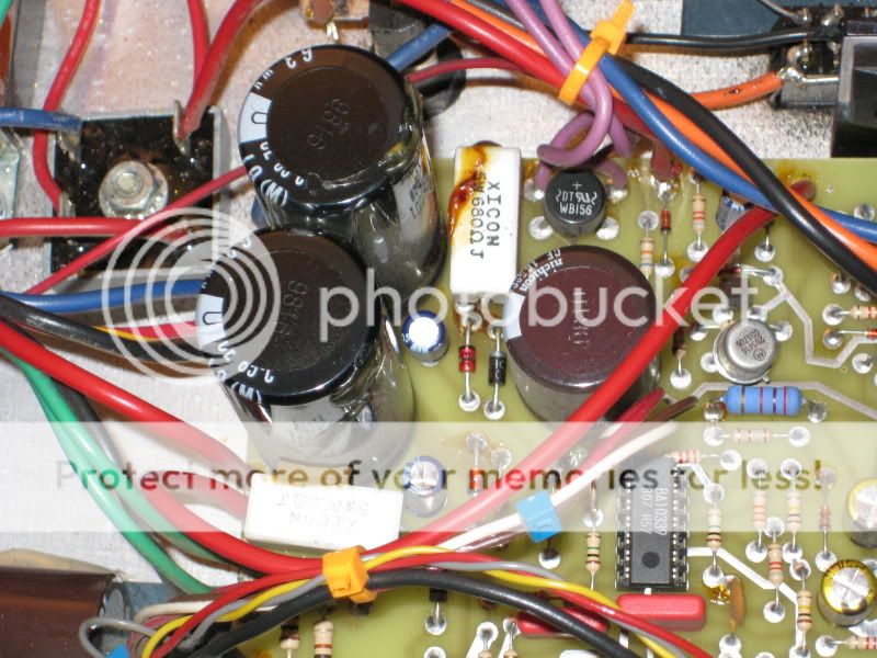
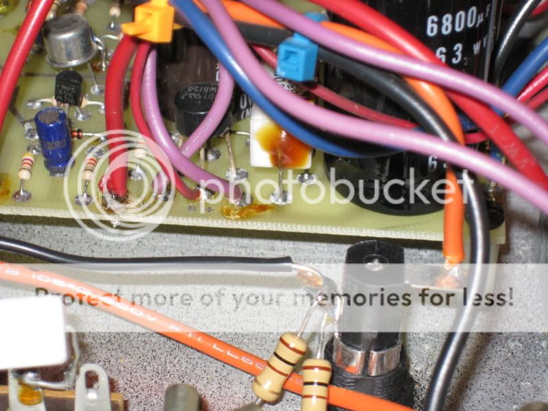
A custom transformer is required here, as the 6.3V and 182V windings are what is used to power the tube preamp stage. The other alternative would be two separate transformers but I'm not sure where you'd find a transformer with 182V/6.3V secondaries. The power amp stage could be powered from a 2x45VAC secondary transformer. I couldn't judge what VA rating you'd need without knowing the original transformer's size.
The brown stuff you're seeing is flux residue from where the wires were soldered, or glue, or possibly both!
If you wire these primaries out of phase it will draw a lot of current. This does not necessarily mean the transformer is shorted.
A custom transformer is required here, as the 6.3V and 182V windings are what is used to power the tube preamp stage. The other alternative would be two separate transformers but I'm not sure where you'd find a transformer with 182V/6.3V secondaries. The power amp stage could be powered from a 2x45VAC secondary transformer. I couldn't judge what VA rating you'd need without knowing the original transformer's size.
The brown stuff you're seeing is flux residue from where the wires were soldered, or glue, or possibly both!
Mooly - thanks, I didn't think about the impedance at 60hz.
I will go ahead and diconnect the secondaries and see if it still blows a 3 amp slo blo fuse.
And for my own clarification - am I to check resistance across the output transistor leads?
Also, is appears that the rectifier is that black square thing. I need to disconnect the wires and check resistance? Is it like a four diode thing encased in potting?
Jaycee - that sounds very reasonable to have a multi input for different voltages.
I guess all I really need is what's shown on the spec sheet.
But as you point out, I have no idea what capacity is required.
Yes, that's what I thought that brown stuff was too.
Some looks like flux (but a LOT) and some was definately glue (they glue those to filter caps together).
Another question;
These filter caps are 6800.
On tube amps they seem to be in the 20 to 100 range at a much higher voltage.
When these get old and fail they can fry the PT.
Is that also true for solid state amps?
Are these suspect as well in my case here?
Check from middle transistor lead (collector) to the emitter (right hand lead as viewed from front/top). Usually fail short.
When reading for shorts you can test in circuit (the bridge). If it's short it's short")
Filter caps are much larger value in solid state because higher currents at lower voltages are involved. Higher current drawn = more ripple. They usually fail by presenting a rising E.S.R. (equivalent series resistance) rather than failing short or leaky.
When reading for shorts you can test in circuit (the bridge). If it's short it's short
Filter caps are much larger value in solid state because higher currents at lower voltages are involved. Higher current drawn = more ripple. They usually fail by presenting a rising E.S.R. (equivalent series resistance) rather than failing short or leaky.
It looks like the output devices have been replaced before, because of the rosin left over from the solder job. None of the other solder joints on the board have that residue. Also I suspect that the goop all over the square white resistor is from the big filter cap next to it. When electrolydics in a power supply go the somtimes puke their guts out. If this is the case it could make a bad smell, blow the fuse ect. Good news is that if the diode bridge and the output transistors are still good, this won't cost too much to fix.
First step is to check for shorts like Mooly said.
First step is to check for shorts like Mooly said.
I took the advice and disconnected the secondaries to verify the tranny was burnt and yes - it's toast.
So if I can't find a generic transformer I'm gonna have to get it from Mercury Magnetics for 150 bucks.
I checked the output transistors and they're not shorted.
I assume they were previously replaced because of the smeared thermal paste.
(and because it was previously worked on because it died once before)
My plan would be to put four, in-line fuses for the secondaries.
I found an SWR schematic for the power supply used for "all models".
The green are the filament and it shows a 4 amp internal fuse but the amp I have doesn't seem to have that fuse. But I will use a 4 amp on those.
The purple go to a "1 amp" four diode, rectifier and has a 100uf filter cap. So a 1 amp fuse for those.
And then the red are the high current ones that are basically 45v going to a diode rectifer that says "15A". But the wires that come out of the transformer are the same gage as the input. And it can never attain that much current because it will blow the 3 amp (120v) fuse. So I figure an 8 amp fuse on each of the red wires. (The center tap between the two is ground).
This way everything is protected.
COntact Fender and ask if they have any of the transformers left. If they do, you can order one through any Fender dealer or from fenderparts.com. They won;t sell direct. If they no longer have them, oh well.
Those outputs could still be originals, as far as I know the board is mounted and the outputs installed after the fact rather than try to get the right elevation for the parts to meet the mounting holes. That may be original flux. See if the transistor date codes agree with the rest of the amp. Not that it matters, if they are bad they are bad, either way.
Those outputs could still be originals, as far as I know the board is mounted and the outputs installed after the fact rather than try to get the right elevation for the parts to meet the mounting holes. That may be original flux. See if the transistor date codes agree with the rest of the amp. Not that it matters, if they are bad they are bad, either way.
Fender aquired SWR in 2003.
The Basic Black amp was discontinued in 1999.
It appears that SWR used Mercury Magnetics as original equipment.
The "SCHEMATIC PRIMARY WIRING DOMESTIC & EXPORT ALL MODELS" REV C dated Feb 22, 1990 calls out the transformer for the BABY/ELECTRIC BLUE amps as p/n 560005 which is also listed in the Mercury Magnetics web site.
They didn't mention the Basic Black amp on the PRIMARY schematic but it is mentioned on the "SCHEMATIC SECONDARY WIRING PREAMP/POWER CLIP CIRC. ALL MODELS" REV C attached to primary schematic and dated Feb 6, 1991
Also, I saw a picture of a different Basic Black amp and it had a Mercury Magnetics in it too - but it looked nice and straight - the one in this amp looks warped/wavy on the sides (melted inside?).
So I'm coming to the conclusion that I'll have to buy a Mercury Magnetics transformer.
Unless someone can tell me where I can find a generic.
I was hoping I could since the Basic Black was SWRs most popular combo from 1992 to 1999.
The big problem is the 182v secondary for the tube. Otherwise i'd suggest using two seperate transformer, one for the tube stage and one for the power stage. Hammond Manufacturing have a nice range for tubes:
Hammond Mfg. - "Classic" Low Power/Bias Transformer - (261-262 Series)
I'm wondering if a 120V secondary would work, but I dont know anything about tubes to know if the lower voltage would run the preamp stage OK.
For the power stage, an off the shelf transformer with 80VCT windings (or 2x40V) should work OK. Better still a 2X45V (90VCT) if you can get one.
Yes, I also thought about multiple transformers - but didn't know where to find them.
I was looking through Mouser and the cost of three isn't much cheaper.
But this Hammond site looks promising. Thank you.
The 182v secondary creates 250vdc after the rectifier and filter capacitor.
This is the B+ for the tube - I think lowering it will lower the gain of the tube circuit too much.
I'm gonna look through Hammond's stuff now.
- Status
- This old topic is closed. If you want to reopen this topic, contact a moderator using the "Report Post" button.
- Home
- Amplifiers
- Solid State
- SWR Basic Black fried PT