My build guide says not to install C5,C6(2200PF),R8,R15.They are not required anymore.
then continues with...1.The power amplifier can be configured as a DC amplifier.To do so the feedback resistor 220uF is to be replaced by a zero ohm jumper (say a bare copper wire)so the amplifier can be down to 0Hz.
And thats where I am right now.I still have to install the many transistors but can't get to it till Monday.
Last edited:
janusz i notice in post #18 you stated "...Note:
1. W2 - omitted
2. "***" = 220 ohm..."
My board is version 1.2
Do you think I should omit W2?
What does line number 2 mean?
Its pretty confusing to get an amp kit with parts and a poor quality schematic available only online which I do not seem to be able to get a decent print of.
The schematic you provided is much better quality than what I had to work with.
Hope your amp works first time you power it up.
I'd love to see some pics of the amp and power supply.
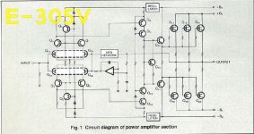
Who claimed the Diamond is an Accuphase E-305 clone?
I have just downloaded the E305 service manual, and except for the three output transistor pairs they have nothing in common.
Be careful with DC output if you are not using DC protection and did not put that 220uF capacitor on the feedback. Don't be greedy at first, because using a full-DC amplifier can be dangerous for your speakers and the amp if you are not careful.
Also be careful when first firing it and use some resistors on the power line to protect the output transistors. Remember it was claimed on this topic that those transistors could be fake.
carlmart thank you for the warning.
Here is the link to the Accuphase reference:http://www.ebay.com/itm/Diamond-dif...557?pt=LH_DefaultDomain_0&hash=item335e9b7195
Here is the link to the Accuphase reference:http://www.ebay.com/itm/Diamond-dif...557?pt=LH_DefaultDomain_0&hash=item335e9b7195
Last edited:
"***" - two resistors, namely R16 and R28 have such markings on the pcb v1.4. Removing W2 and R28 and making R16=220ohm simplifies the circuit. I do not know the reason for this. From simulation R16=220ohm (no R28 and W2 in the circuit) gives offset close to zero but if you set W2 with R28 in series and R16 in parallel to give 220ohm as a starting point for potential further regulations of the offset it should be OK. Potential problem is that trimers may loose contact and offset would jump a lot plus other problems.
The first thing: check if R22 and R23 are floating, that is if their centre is not connected to the output path between power transistor emitter 0.22 ohm resistors. If so then before soldering power transitors onto the board wire shorten the point between R22 and R23 with a pont between R46 and R49 on the output path and connect power to the amp through a test bulb circuit. Then set voltage drop accoss R3 to 2.5V using W1, then using W2 set offset to zero and using W3 set voltage at R22 to be below 500mV. Check R3 voltage again and at other points as well.
If all is OK then desolder the shortenning wire, solder power transitors onto the board and power up the amp through the test bulb circuit. If it does not light up it's ok. I mean it may lighten up for a moment when PS caps charge and then it will go off. If it does not go off disconnect the amp as there is something wrong. If it goes off adjust offset again and set current through the 0.22 emittter resistors to 50mA (10mV accross) and if you have large heatsinks it can go up to 100mA or 20mV across.
cheers,
Last edited:
Here is the link to the Accuphase reference:Diamond differential power amp kit spk protection pair! | eBay
The one that claims that is Jim's Audio, so don't take them seriously.
In fact their selfish and uncommercial policy of only showing their schematics IF and ONLY you buy their products is stupid and unprofessional.
They are cloning or being based (according to them) on an existing commercial product, so they HAVE to show you first what the schematic is, even if they do not fill any values for the parts, like serious people like Borbely used to do.
Jim's Audio is a joke, I think, for a company that intends to create commercial interest on their products. They behave as if they were Jeff Rowland or some serious top company.
Well, it seems that Jim's Audio is starting to review their commercial attitude.
Now their Diamond Differential kit does bring the amp schematic from where the amp is supposed to come.
They also wrote on the JC-2 preamp thread, here on DIYAudio, what their kit consisted of.
That is the transparent policy we need to know what we are buying from them.
Pity the Diamond Differential kit is not completely based on the Accuphase E-305V, that is the input and VAS stage seem to be similar, but there are two important modifications from the original:
1) The output is bipolar and not MOSFET.
2) There is no DC servo.
In any case, kudos for what it seems Jim's Audio new policy.
Has anyone sucessfuly built it?
I have finished it some time ago but failed to make it operational. When setting bias current once it exceeds 10mA it starts to rise by itself and the amps begins to suck in current. As the amp was connected to the mains via current limiting bulb there was no fire, no smoke.
Interestingly, all transistors stayed cool or warmish. Zoebel resistor was also cold. First I thought this might have been the result of oscillations as VAS is quite susceptible to such (LT spice tests) but zoebel resistor stayed cold. I have no oscilloscope at home so could not check it. It might be bias regulation circuit. I'll replace bd139s with SC5171s.
Any other suggestions?
cheers,
Bummer this problem you're having, Janusz.
Have you tried both channels or just one?
I now realized the bias transistor is not the one shown on their schematic (2SD669).
Do tell me what happens with the 2SC5171.
My guess is the VBE transistor is not tracking temperature as it should, because the transistor is dead or because the contact with the heatsink is not complete. Have you checked that?
The multiplier Q must be Thermally connected to the output Qs or their heatsink.
The Multiplier Q must be Electrically insulated from the output Qs and their heatsink.
Just glue a To92 or E-line or sot23 to the heatsink or to the Collector leadout right next to the plastic package.
The Multiplier Q must be Electrically insulated from the output Qs and their heatsink.
Just glue a To92 or E-line or sot23 to the heatsink or to the Collector leadout right next to the plastic package.
I tried both channels separately. I have separate toroids and PS for each module and somewhat improved PS to VAS and LTP so I can activate only IS. Here setting up voltages was no problem once I have fixed some pooor soldering on one transistor. Both channels show exactly the same behaviour which indicates potential design problem.
Well, placing the multiplier on one of the power transistors somewhat improves thermal tracking but what I observe is no increase in power transistor temperature as bias climbs up and PS voltage drops. Transistors are rather coolish. Actually only some transistors in VAS get warmer but one would expect ths.
During the weekend i'll replace the multiplier bd139 transistor with sc 5171.
Any other suggestions?
All transistors are well bolted to heatsinks. I'll send you a photo.
cheers,
I tried both channels separately. I have separate toroids and PS for each module and somewhat improved PS to VAS and LTP so I can activate only IS. Here setting up voltages was no problem once I have fixed some pooor soldering on one transistor. Both channels show exactly the same behaviour which indicates potential design problem.
If you followed the steps correctly for the first stages, it's quite likely the problem is on the next stages: VBE, drivers and output.
Well, placing the multiplier on one of the power transistors somewhat improves thermal tracking but what I observe is no increase in power transistor temperature as bias climbs up and PS voltage drops. Transistors are rather coolish. Actually only some transistors in VAS get warmer but one would expect ths.
During the weekend i'll replace the multiplier bd139 transistor with sc 5171.
Any other suggestions?
All transistors are well bolted to heatsinks. I'll send you a photo.
My guess is the VBE, drivers and output bipolars might be fakes. Have you tested them all on a DMM to see if their HFE checked with the data sheet?
Things I would try:
1) Replace the BD139 for another BD139. I don't see the point in going for that other transistor.
2) Get another pair of output transistors, that you are sure are not fakes, just one single pair, and solder them to the amplifier. Take the others out, and see what happens.
Another thing, unlikely, might be problems in the voltage rails pcb tracks going to the output. Have you checked voltages?
If it doesn't work, then it's time to get in contact with Jim's Audio or Tubeshunter, which are the ebay shops selling the Diamond Differential kit.
They are quite likely reading this thread, and I think this forum can influence people not to buy specific kits. So they better help us solve this problem.
Who claimed the Diamond is an Accuphase E-305 clone?
I have just downloaded the E305 service manual, and except for the three output transistor pairs they have nothing in common.
It is like a E-305V, a different amplifier.
It is like a E-305V, a different amplifier.
Like Jim's Audio now shows on eBay, this is supposed to be clone for the E305-V.
But even so there are two important differences on the clone: the output is bipolar; there's no DC servo.
Attachments
Like Jim's Audio now shows on eBay, this is supposed to be clone for the E305-V.
But even so there are two important differences on the clone: the output is bipolar; there's no DC servo.
Not a clone. He says: "This kit is reference to E-305V", so it's NOT a clone.
Note: I have no affiliation with Jim's Audio. I'm just a satisfied customer.
I'm interested in his other diamond input kit:
Hi-speed power amplifier sp-protect MOSFET o/p Mimesis! | eBay
but not sure what I want to do yet.
I prefer to order just boards to avoid the issue of fake parts. But, sometimes I run up against serious problems, like when the schematic calls for obsolete parts and I have no choice but to order them off of eBay. I just cross my fingers and hope for the best.
Last edited:
No one says on eBay what they are selling is a clone of a commercial product, present or past.
Whatever the word they use (resemblance, reference, inspired on) it's only a matter of semantics. If the people who should be buying the kit do not read on what existing product is it based, they wouldn't buy it. So that characteristic has to be quite clear.
At the beginning of this thread it was discussed why was it called Diamond differential, and some comparisons were made with Sansui amps. But they were not. I still do not know the reason for the name.
- Status
- This old topic is closed. If you want to reopen this topic, contact a moderator using the "Report Post" button.
- Home
- Amplifiers
- Solid State
- DIAMOND DIFFERENTIAL INPUT POWER AMPLIFIER EBay kit