Diode,
May I also please have a copy of the article. My email id is cred@rediffmail.com.
How many watts can this amp pump into an 8 ohm load at the highest voltage possible with this schematic?
May I also please have a copy of the article. My email id is cred@rediffmail.com.
How many watts can this amp pump into an 8 ohm load at the highest voltage possible with this schematic?
Hi HB,
Yes I used the layout that you posted, however as stated I did change some numbering to match the parts list that Diode provided. There were also a couple of small mistakes with componant placement such as the diode on the positive rail and LS o/p being around the wrong way and the same diode on the negative side missing altogether (there might be more but thats all I can remember off the top of my head).
These problems were easily spotted on careful inspection.
And the board fired up fine the first time out, I have a dual 15v current limiting bench supply so power up was much less risky (far to many active componants to lose their magic smoke") ).
).
Anyway all told a very nice layout.
P.S. I did remove the LED and smd resistor that had been added to each rail (not much point on indicators in a closed case!)
I will try and add all of my changes and post the layout back on this tread.
Yes I used the layout that you posted, however as stated I did change some numbering to match the parts list that Diode provided. There were also a couple of small mistakes with componant placement such as the diode on the positive rail and LS o/p being around the wrong way and the same diode on the negative side missing altogether (there might be more but thats all I can remember off the top of my head).
These problems were easily spotted on careful inspection.
And the board fired up fine the first time out, I have a dual 15v current limiting bench supply so power up was much less risky (far to many active componants to lose their magic smoke
).Anyway all told a very nice layout.
P.S. I did remove the LED and smd resistor that had been added to each rail (not much point on indicators in a closed case!)
I will try and add all of my changes and post the layout back on this tread.
Waiting
Hi guys,
I am really considering this amp as my next project. I will be waiting for matth's post regarding the board he used and any changes he did.
If any of you guys have any other information (schematics, pcb layouts, parts placement etc.), can you please send it to me by email at ndijamco@edsamail.com.ph
Thanks in advance!
JojoD
Banned
Joined 2002
Hi JasonL,
Thanks, I don't like to think of how much this amp cost, if I do maybe I'll give up diy and buy a commercial offering
My overal project is a PA system for discos, this will consist of 4 vented sub enclosures with 15" subs and 4 flyers containing 1 12" mid-bass and 1 wide despersion horn tweeter. The subs will have a top-hat in the top and the flyers will have a top-hat in the bottom with a pole between them.
I will build 4 of these amps, two will run at 78-0-78dc and will power the 4 subs and two will run at 58-0-58dc and run the flyers.
The system will be bi-amped using the 2way LR crossover design on westcoastsound.
The speakers are sat in my shed at the moment having been roughed out, this weekend is sub finishing time!!
When all is finished I will post pics of the entire system, until then 3 more amps to be built and 2 more flyers.
Banned
Joined 2002
For all that wanted the revised Traxmaker layout, here it is.
I have added a missing diode and moved some componants that where incorrectly placed, I have also changed the labels on all active componants to match the circuit diagram amd parts list.
Please note that all passive componant labels are wrong but the value label is correct.
I would advise you all to check this layout yourselves before construction, but I think that I have changed everything I caught during construction (and my amp works ).
).
If you need Trakmaker it can be downloaded in trial form from:http://www.circuitmaker.com/downloads/trial_version/form_trial_registration.asp
I have added a missing diode and moved some componants that where incorrectly placed, I have also changed the labels on all active componants to match the circuit diagram amd parts list.
Please note that all passive componant labels are wrong but the value label is correct.
I would advise you all to check this layout yourselves before construction, but I think that I have changed everything I caught during construction (and my amp works
).If you need Trakmaker it can be downloaded in trial form from:http://www.circuitmaker.com/downloads/trial_version/form_trial_registration.asp
Attachments
JasonL said:Well Congrats and good luck. How come you didn't try the av-800's from e-holton. Im building 2 of them but not yet as i need a job to buy the part's..
Yeah, I've looked at the Saints amps a lot.
I wouldn't build the AV800 as the semis are quite hard to source in the UK. I did however design my own PCB layout for the Lateral mosfet amp. I built two of these and when they were still on the bench disaster struck; I shorted one with my test probes (now I know why people include test point pins) and the other smoked itself due to poor gnd wiring on the bench (I think there was a bad gnd loop that was causing it to oscillate and it went pop when I attached a load) after that I always use my scope when bringing amps up (my fualt for being lazy).
I think that after I have completed these amps I will resurect those boards and try again, if all goes well I will shared the layout.
Banned
Joined 2002
Anthony's instructions for a newbie SUCK. i bought the n-channel 2 year ago and was so confused. i'm glad my dad was around as he used the scope to show me what was happening at power up. anthony didn't show or tell me that i needed resisters underneath at all. the amp when it was done is very strong and powerful .. don't as me why i'm building the av-800s but it will be a challenge.
To answer a few questions at once,
The amp works well, as designed, with MJL's as drivers. I also built one using 2SA1943 and 2SC5200 for outputs and it also works great!
I posted RCS Radio as the website to look at for boards. He is in Australia buit ships all over the world. Board number is SC01208971.
I haven't scanned the entire article yet but when I do, I will e-mail it to who wants it. My question on ethics to you all.... Silicon Chip Magazine doesn't offer any back issues of this project for sale. Dick Smith Electronics doesn't sell the kits any more. They told me not to post the article on any web site as they had big problems with me doing it. I don't get it.... Someone throw me a bone here. Do you all see any problems since the above issues are in the process? I don't want to make them mad but at the same time, I see no harm as that article was in 1996 and it's just that, now, an article in an old magazine. My feelings...... SO WHAT?!!! Other opinions please.
I have considered building the AV-800, in fact, that's the one I wanted to build but couldn't find FET's or cheap source. Matching is a big problem if you don't buy a couple of tubes of them. Great project, just little consideration to the average DIYer and someone who is fairly limited on funds. Nice big torroid transformers are very expensive here in the US, I don't know about Europe and Australia. An electrically hot heatsink is a really bad idea and dangerous even to experienced technicians. I get them sometimes in my work and curse the engineers who do it.
My MJL's cost me nothing as I sampled them from ON Semiconductor. My 2S transistors cost me $78.00 US for 10, but there are much cheaper places to find them. My boards, 2 of them, cost me $50.00 US including shipping. I easily have $200.00 US in mine but I'm lucky in that I work at a repair shop and my boss sold me one of my transformers for $20.00 US and the other one he gave me for free as the temperature fuse on the input had blown anf I fixed it without the fuse. My transformers came from Peavey but not 80V rails. He also gave me 36000uF per rail of capacitors but only for one of the amps. I'm still looking for caps for the other one.
Chris
The amp works well, as designed, with MJL's as drivers. I also built one using 2SA1943 and 2SC5200 for outputs and it also works great!
I posted RCS Radio as the website to look at for boards. He is in Australia buit ships all over the world. Board number is SC01208971.
I haven't scanned the entire article yet but when I do, I will e-mail it to who wants it. My question on ethics to you all.... Silicon Chip Magazine doesn't offer any back issues of this project for sale. Dick Smith Electronics doesn't sell the kits any more. They told me not to post the article on any web site as they had big problems with me doing it. I don't get it.... Someone throw me a bone here. Do you all see any problems since the above issues are in the process? I don't want to make them mad but at the same time, I see no harm as that article was in 1996 and it's just that, now, an article in an old magazine. My feelings...... SO WHAT?!!! Other opinions please.
I have considered building the AV-800, in fact, that's the one I wanted to build but couldn't find FET's or cheap source. Matching is a big problem if you don't buy a couple of tubes of them. Great project, just little consideration to the average DIYer and someone who is fairly limited on funds. Nice big torroid transformers are very expensive here in the US, I don't know about Europe and Australia. An electrically hot heatsink is a really bad idea and dangerous even to experienced technicians. I get them sometimes in my work and curse the engineers who do it.
My MJL's cost me nothing as I sampled them from ON Semiconductor. My 2S transistors cost me $78.00 US for 10, but there are much cheaper places to find them. My boards, 2 of them, cost me $50.00 US including shipping. I easily have $200.00 US in mine but I'm lucky in that I work at a repair shop and my boss sold me one of my transformers for $20.00 US and the other one he gave me for free as the temperature fuse on the input had blown anf I fixed it without the fuse. My transformers came from Peavey but not 80V rails.
He also gave me 36000uF per rail of capacitors but only for one of the amps. I'm still looking for caps for the other one. Chris
I think you are lucky then...being able to work at a repair shop...perhaps I will go that way when I grow...I'm currently 14...and I dun "play" like most kids do...haha...I wave soldering irons when I'm free...do I need any qualifications to be a repairman?? okok...back to the amp...where did you get the boards??
Hi
Dioded,
It seems that I can't make my own board since the largest photo pcb I can buy is 12X12 inch.
I don't see how it can hurt them. If they have any intention of selling back issues of the mag, maybe. But if not then why would they stop you?
Anyway, if you do scan them, please remember me .
.
My email is ndijamco@edsamail.com.ph
Cheers,
JojoD
Dioded,
It seems that I can't make my own board since the largest photo pcb I can buy is 12X12 inch.
I don't see how it can hurt them. If they have any intention of selling back issues of the mag, maybe. But if not then why would they stop you?
Anyway, if you do scan them, please remember me
.My email is ndijamco@edsamail.com.ph
Cheers,
JojoD
Hi Jojo,
The board layout I posted will just fit onto a 12" piece of board.
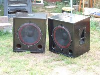
I said that this weekend was Sub finishing time so here are half the results. Just need to add the hardware to the other two cases.
I know this isn't the forum for these , so I will start a new thread when all are finished .
Just a sneek preview.
The board layout I posted will just fit onto a 12" piece of board.
I said that this weekend was Sub finishing time so here are half the results. Just need to add the hardware to the other two cases.
I know this isn't the forum for these , so I will start a new thread when all are finished .
Just a sneek preview.
Attachments
Hi All,
I just finished scanning the SC article and it is a LOT. Total is about 4 MB and 15 pages long or so. Please give me time and space to get it all to you........
Why not post it. I'm trying to be respectful to their wishes. I'm sure they have their reasons. NO! I'm not afraid to post it....
Chris
I just finished scanning the SC article and it is a LOT. Total is about 4 MB and 15 pages long or so. Please give me time and space to get it all to you........
Why not post it. I'm trying to be respectful to their wishes. I'm sure they have their reasons. NO! I'm not afraid to post it....
Chris

li_gangyi said:I think you are lucky then...being able to work at a repair shop...perhaps I will go that way when I grow...I'm currently 14...and I dun "play" like most kids do...haha...I wave soldering irons when I'm free...do I need any qualifications to be a repairman?? okok...back to the amp...where did you get the boards??
me too
im 15, and all my freinds spent the weekend playing footmall, i spend it in my garage soldering Diode said:Hi All,
I just finished scanning the SC article and it is a LOT. Total is about 4 MB and 15 pages long or so. Please give me time and space to get it all to you........
Why not post it. I'm trying to be respectful to their wishes. I'm sure they have their reasons. NO! I'm not afraid to post it....
Chris
could i have a copy? matttcattt@yahoo.co.uk thanks loads.
- Status
- This old topic is closed. If you want to reopen this topic, contact a moderator using the "Report Post" button.
- Home
- Amplifiers
- Solid State
- Driver heatsink on 500w amp