It is good to make use of input stage gain.
Because it is good linear gain.
This is an idea I have tested and had since years ago.
I call it new, because I have never came across this before
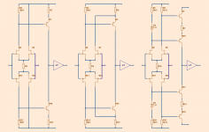
See diagram.
----------
Input may as well be 4 BJT and not necessarily symmetrical.
* First does not take gain from U5/U12 in input pairs.
* Second feeds U7/U14 to emitter of VAS transistors
This gives some extra gain. Curl has used it.
* Third is my idea. Uses a complmentary pair. For BJT VAS we need voltage sources to set current in VAS.
- This gives almost twice the gain of first circuit.
- Also voltage supply can be separate from input stage.
This can be of benefit.
Because it is good linear gain.
This is an idea I have tested and had since years ago.
I call it new, because I have never came across this before
See diagram.
----------
Input may as well be 4 BJT and not necessarily symmetrical.
* First does not take gain from U5/U12 in input pairs.
* Second feeds U7/U14 to emitter of VAS transistors
This gives some extra gain. Curl has used it.
* Third is my idea. Uses a complmentary pair. For BJT VAS we need voltage sources to set current in VAS.
- This gives almost twice the gain of first circuit.
- Also voltage supply can be separate from input stage.
This can be of benefit.
Attachments
I've tried this topology, though with single diff pair input stage.
It has great speed, but thermal drifts make balance, and particularly offset control, very tetchy.
The degen resistor between the emitters of the Rush cascode is critical as it sets transconductance.
I had more success using the RC in the input stage, rather than as VAS.
Hope this helps,
Hugh
It has great speed, but thermal drifts make balance, and particularly offset control, very tetchy.
The degen resistor between the emitters of the Rush cascode is critical as it sets transconductance.
I had more success using the RC in the input stage, rather than as VAS.
Hope this helps,
Hugh
Hi Bonsai,
Neither strictly.... a single LTP, terminated with dissimilar resistive loads, driving a RC with degeneration. Sadly, I can't recall all the details, it was more than ten years back, but I do recall that in closed loop the sound quality was ordinary, even properly compensated, and the offset control was poor. I moved a few years later, at the suggestion of Keantoken in fact, to the use of the Rush Cascode in the input stage. This proved better, both in terms of stability and SQ.
I think it's possible to get almost any topology to work well, but there is no doubting that some are better than others. Making that call is tough; when do you stop development and move on?
looks like your input gm would not be very stable, since your LTP tail currents would be changing with the input signal.... LTP tail current should be stable, which is why CCSs are used. there are also stability problems when driving VASs in series like that. a stable operating point would be difficult to pin down here. it probably would work "ok" with real components because tolerance variations would unbalance it enough to stabilize, but using matched components will make it unstable. on the other hand allowing it to work in an unbalanced and more stable condition will also increase distortion a bit. so it's a tradeoff, distortion or instability.
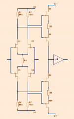
For better thermal, R8, R9, R10 could be split into four. See my failed VL83 schematic that I posted about few month ago at "Its 2010 what your favourite VAS" or something like that, also attached at my VL85 cheapamp my lonely thread.
The center pic at first post VAS is very good and very low gain if Re is split into two with input from center. For facing my crazy supply ripple, using crossed current feedback input with only 1.6x gain, it work great.
The center pic at first post VAS is very good and very low gain if Re is split into two with input from center. For facing my crazy supply ripple, using crossed current feedback input with only 1.6x gain, it work great.
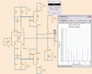
ALL JFET Example
A nice example. All JFET.
All 2SK170BL, 2SJ74BL runs 6 mA. Output single end, too.
Gain is 1 = follower.
Level for test is +/-4 Vpeak, 1 kHz.
All 4 JFET in VAS runs with 12 Volt across each.
THD is very low.
2nd at -131dB
3rd at -138dB
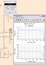
4 caps for compensation gives a nice AC analysis.
See image 2.
-3dB at around 5 MHz
Enjoy
A nice example. All JFET.
All 2SK170BL, 2SJ74BL runs 6 mA. Output single end, too.
Gain is 1 = follower.
Level for test is +/-4 Vpeak, 1 kHz.
All 4 JFET in VAS runs with 12 Volt across each.
THD is very low.
2nd at -131dB
3rd at -138dB
4 caps for compensation gives a nice AC analysis.
See image 2.
-3dB at around 5 MHz
Enjoy
Attachments
This is the main problem of these things...looks good and simulates good
But will they sound fine?.... only building to listen and compare to a reference and test it using non biased evaluators.
Looks great..no doubts....but there's a lot of things that looks great but are not great.... sometimes sound ordinary as Hugh told.... well..he can say things about as he built.
regards,
Carlos
Hi Lineup!
As far as I can see, you wont get double gain by using complement pairs. Look at it this way: One transistor will need a certain drive to pass a certain current. The other transistor will need an equal amount of drive just to pass the same current. ( which it will have to , since they are in series. )
You might get some linearization of the FETs though.
Thorsten Larsen
The stage is an output buffer. U4, U5 has a very high output impedance. U1 and U2 are both essential here.
U4, U5 has very LOW output impedance if you were to close the loop here.
And twice the potential current swing into a real load as U1 + CCS.
U1 and U2 are absolutely redundant and non-essential if they aren't going
to slew any more current than the stage that drives them.
Here I am with peranders
I don't agree, if you do so, you will degrade OLG, rise the output impedance and rise the distortion significantly. With the same OPS, slew depends to a great extent on how weak or hard is the drive, that means how high or low is the output impedance of the driver.
Cheers
Arturo
U4, U5 has very LOW output impedance if you were to close the loop here.
And twice the potential current swing into a real load as U1 + CCS.
U1 and U2 are absolutely redundant and non-essential if they aren't going
to slew any more current than the stage that drives them.
I don't agree, if you do so, you will degrade OLG, rise the output impedance and rise the distortion significantly. With the same OPS, slew depends to a great extent on how weak or hard is the drive, that means how high or low is the output impedance of the driver.
Cheers
Arturo
OLG (voltage) is not increased by a source follower. Go figure...
And unfortunately neither is this specific example giving us any
current gain...
I agree about slew, thats why the driver stage is better here:
His output stage abusing same JFET at exactly same current.
Yet pulling SE against fixed CCS, is only half as capable as the
push-pull circuit that is driving it. Defeats its own purpose...
Last edited:
- Status
- This old topic is closed. If you want to reopen this topic, contact a moderator using the "Report Post" button.
- Home
- Amplifiers
- Solid State
- LINEUP Input-VAS, idea