i did some digging around for an audio amp schematic using a single 2n3055 in the output and much to my surprise, i couldn't find any.
im looking for something simple to build as a utilitarian amp for PA use for example. yes, there are other ways to go about this but i want to use a single 2n3055 in the output.
anybody got any links to some schems?
im looking for something simple to build as a utilitarian amp for PA use for example. yes, there are other ways to go about this but i want to use a single 2n3055 in the output.
anybody got any links to some schems?
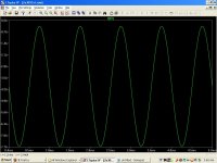
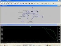
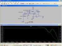
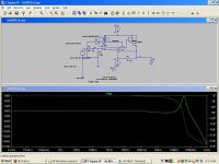
Loop response, Loop response 2p feedback cap, Loop response 50p feedback cap
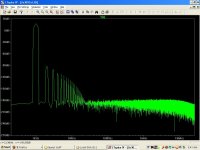
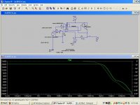
Frequency response 2p feedback cap.
Frequency response 2p feedback cap.
Attachments
"A second 2N3055 is cheaper than a transformer. Cheaper than a 25 watt resistor, too"
There still many fakes TOSH 2N3055 much cheaper than TIP3055.
Hi, RJM1, any opamp like TL071 will also work fine. It is ClassA, no crossover and already with high linearity, weaken the feedback or using feedback from 2n3055 base (with base resistor) output may also has better sound, even with lower linearity.
Go look at the Pass Zen amplifier for inspiration. You can safely replace the MOSFET with a bipolar resistor but of course with some changes in the component values. You should be able to replace the current source with a Resistor of about 10-20 ohms (or a suitable bulb with the requisite resistance). Trimmer pot should be at its minimum at turn on and adjusted to give an idle current of around 1.5-1.8 amps. I would place a 0.5ohm resistor at the emitter of the 2N3055 and use that to measure the current (V=IR, so for 1.8 amps and 0.5 ohm resistor, this would give 0.9V across it). You will need a HEFTY heat sink as this thing runs reallly hot.
I have one of these done up using the 2N3055. It sounds pretty good considering the low cost of parts and the simplicity. Bass is good, but I highly recommend good capacitors, Elna cerafines with 10000uF and 50V rating would work fine as output caps. It does not sound as fast as a MOSFET circuit but it has nice warmish sound somewhat like a tube-amp but with good definition and detail (definitely impressed my "audiophile" friends). I have tried with and without feedback and still prefer without feedback.
As gain is low, you should be looking at an appropriate preamp to go with it. The Bride of Zen would be a good accompanying project. (The BOZ will bring back some speed to the sound without interfering with the niceness of the tone)
There is a turn on thump, so you should be thinking of a delay circuit.
http://www.passdiy.com/pdf/zenamp.pdf
The part of the schematic of interest is the lower half of the circuit involving the IRF 140 only. The 9240 and MPSA part are the current source circuit, which help to linearise the circuit but which I replaced with a load resistor/bulb as in the Zenlite series of amplifiers)
Last edited:
If "reasonable efficiency is required", one transistor isn't the way to go. And a little single ended class A amp requires big heavy and expensive compenents to go with that cheapo 3055. If the objective is to build a SE-A amp because you like the particular sonics, that's one thing. Remember, these things are heaters and the transistor is the cheapest part. If you're looking for a cheap easy way to use a 2N3055 to put out a few tens of watts I stand by the original recommendation.
Hi
John Linsley Hood considered this with his Class A (search in diyaudio). An emitter (or collector) resistor is only about 12% efficient, so you won't get a lot of power for PA like that. You might get 1W from a stage using an 8 ohm load resistor. 8 ohm speaker, which has to run from 14V (dissipation 12W, effective efficiency 8%). I've used transformers for single device outputs with about 30% efficiency. Yes, the cost is high these days for a transformer compared with a push-pull stage.
I would not change the 2n3904 for a TIP31 driver. Quite often such types of transistor are specified for drivers, but the TIP31's are epi devices with fT's around 3 MHz. I'd recommend a higher frequency driver like BD140 or (in TO39) 2N4036 etc if you like old tin cans.
John
i did some digging around for an audio amp schematic using a single 2n3055 in the output and much to my surprise, i couldn't find any.
there's a reason for that. You could copy some of the most earliest semiconductor designs ie car radio, but they will mostly use a big expensive germanium power PNP and an output transformer. so you'd have to flip it around a bit adapting to a NPN. By the time of 2N3055 device, audio topologies have moved on to class B and AB, first using transformers, then without using quasi PNP w/ either split supplies or DC coupling (err, blocking) caps.
w/o a standard classic output transformer, you are in custom territory. w new class A load lines for yer Vcc Ic.
Last edited:
The Tip31 was because it has to dissipate about 3W.
You really don’t want to do that. With an ft of .8 MHZ on the 2N3055 if your driver stage can go far beyond this you are just asking for major oscillations.
An externally hosted image should be here but it was not working when we last tested it.
john_ellis You really don’t want to do that. With an ft of .8 MHZ on the 2N3055 if your driver stage can go far beyond this you are just asking for major oscillations.
The car radio type circuit is the way to go. You only need to get hold of an old valve radio type output transformer, use the secondary as the collector load, don't use the primary (insulate the primary leads to avoid a belt), and then couple to an 8 or preferably 15 R speaker via a capacitor, 2200uF should be enough.
Regards
Henry.
Regards
Henry.
RJM1 -The circuit may already have oscillation problems. The original 2N3055 had 0.8 MHz ft and I suspect one of these WOULD be stable with a high frequency driver.
But the current devices will be closer to 3 MHz. HAving two transistors rolling off at the same frequency may be worse than one while the other maintains a better phase margin. But all this can be optimised.
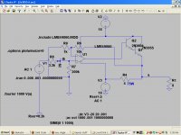
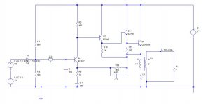
However, in the circuit shown, the driver needs to be able to hold the gain at higher currents in this configuration - nearly 8A peak current ? will need up to 1A drive. Perhaps an MJ21193 to remain more linear at 8A would be better. Or use a transformer for higher efficiency.
But the current devices will be closer to 3 MHz. HAving two transistors rolling off at the same frequency may be worse than one while the other maintains a better phase margin. But all this can be optimised.
However, in the circuit shown, the driver needs to be able to hold the gain at higher currents in this configuration - nearly 8A peak current ? will need up to 1A drive. Perhaps an MJ21193 to remain more linear at 8A would be better. Or use a transformer for higher efficiency.
First pass transformer design:
plates M6 0.35 mm (GOSS)
size EI150 (1.5 inch square section core; =pattern #120; 1.5 inch stack)
Primary: 220 turns 1mm insulated copper wire
Secondary: 220 turns 1mm insulated copper wire
Stacked unidirectional, air gap 1.2mm (use 0.6 mm cardboard spacer)
Inductance ~ 100 mH
Resistance ~ 1 ohm
should not require additional resistor in series.
Probably OK to use bifilar winding method since other approach (1 layer pri-1 layer sec-etc would have almost same capacitance between windings).
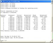
Turns ratio 1:1 should give 15W max rms output but good performance at 10W and below. Simulated distortion .01% at 10W, but excluding transformer. Hence need very tight coupling between primary and secondary.
John
plates M6 0.35 mm (GOSS)
size EI150 (1.5 inch square section core; =pattern #120; 1.5 inch stack)
Primary: 220 turns 1mm insulated copper wire
Secondary: 220 turns 1mm insulated copper wire
Stacked unidirectional, air gap 1.2mm (use 0.6 mm cardboard spacer)
Inductance ~ 100 mH
Resistance ~ 1 ohm
should not require additional resistor in series.
Probably OK to use bifilar winding method since other approach (1 layer pri-1 layer sec-etc would have almost same capacitance between windings).
Turns ratio 1:1 should give 15W max rms output but good performance at 10W and below. Simulated distortion .01% at 10W, but excluding transformer. Hence need very tight coupling between primary and secondary.
John
- Status
- This old topic is closed. If you want to reopen this topic, contact a moderator using the "Report Post" button.
- Home
- Amplifiers
- Solid State
- any single 2n3055 audio amp schems out there?