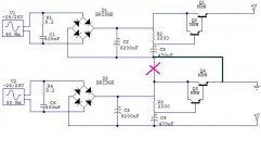
You should add resistors in parallel with the capacitors, to give the transistors more room.I have this supply ready to power a dual rail class A amp. Can this circuit give low ripple, and hold a steady ground for low DC offset?
(EDIT: The lower rail in the picture should read -V, of course)
Substituting a CFP for the darlington has a number of advantages: it improves the ripple rejection marginally, gives a DC output 0.7V higher, but more importantly, it reduces the output impedance by a factor 2.5.
Attachments
the added resistor parallel to the base cap is what makes it a capacitor multiplier.
Without the added resistor, the circuit tries to be a bad voltage regulator.
That added resistor !
Try a series pair of Zener and resistor. You can get cap multiplier action where output voltage tracks (a fixed % of ) input voltage at voltages lower than the "knee".
At input voltages higher than the "knee" the slope of output voltage vs input voltage brings in a little voltage regulation and this prevents excessively high voltages being sent to the client circuit when mains voltage is near maximum tolerance.
almost.
swap the Rs around.
200r to 470r feeding the C
4k7 to 20K in series with the Zener.
And another resistor parallel to the Zener. It is this parallel resistor bypassing the Zener that allows true cap multiplier action.
Add second RC before the first to remove a bit more ripple.
Then the first R is split between the two RCs for a similar total resistance.
That total resistance determines the % of input voltage that the output tries to track.
When the voltage across the Zener is reached, it starts passing current and modifies the slope of Vout vs Vin
Member
Joined 2009
Paid Member
you may like to consider this too (ignore the title - read the section on a fail safe power supply for Class A amps based on dual rail capacitance multipliers)
Long Tailed Pair Zen, A W Newby, Jan 2007
Long Tailed Pair Zen, A W Newby, Jan 2007
You have the simulator, insert some values and see what output V vs input V looks like.
As a starter the Zener can be ~ nominal operating voltage. Changing this value simply moves the voltage of the "knee".
The multiplier sends an output that ~ tracks a % of the input voltage. The resistors determine that %.
As a starter the Zener can be ~ nominal operating voltage. Changing this value simply moves the voltage of the "knee".
The multiplier sends an output that ~ tracks a % of the input voltage. The resistors determine that %.
- Status
- This old topic is closed. If you want to reopen this topic, contact a moderator using the "Report Post" button.
- Home
- Amplifiers
- Solid State
- Capacitance multiplier, suggest improvements