post 39,
the input on the right hand diagram (correct unbalaned to balanced circuit) has ~3k4 of input resistance. The Source must be capable of driving this and all the parasitic capacitances drawing on the Source's output stage.
Hi Andrew
Thanks for the giving the information. Will I have any problem if I use this Unbalance to Balance converter to hook up my CD player and the pre-amp? Please advice.
The first schematic will oscillate! + & - inputs are backwards.
Hi Simon
Thank you for the inputs. Now I feel free to use this circuit to make some pcbs to build my Unbalance to Balance converter.
try it, but I am confused by why you think you need to go from unbalanced at the CDP to balanced at the next receiver and give the CDP at harder job to drive the convertor.hook up my CD player and the pre-amp? Please advice.
What are you gaining?
Try converting the CDP output direct to psuedo balanced. Jensen describes.
Now you can have the advantages of long cables driving balanced input and not need an extra converter and not need to load up the CDP output.
try it, but I am confused by why you think you need to go from unbalanced at the CDP to balanced at the next receiver and give the CDP at harder job to drive the convertor.
What are you gaining?
Try converting the CDP output direct to psuedo balanced. Jensen describes.
Now you can have the advantages of long cables driving balanced input and not need an extra converter and not need to load up the CDP output.
Hi Andrew
I am trying to change my current single ended stereo system to a full balanced one to get the advantages of lower noise and better dynamic by using balanced connections.
I will search a take a look at psuedo balanced which you suggested.
Thank you
this methodology seems to be wrong !I am trying to change my current single ended stereo system to a full balanced one to get the advantages of lower noise and better dynamic by using balanced connections.
this methodology seems to be wrong !
Hi Andrew
So the only solution is to use CD players with balanced output?
I am currently have 3 players, they are Pioneer DV-79AVI, Toshiba SD-900E & Sony DVP-S9000ES all of them only have RCA outputs.
Balanced (and "pseudo balanced," also called impedance balanced) connections solve certain problems, but most such problems generally don't happen in stereo equipment with three-foot-long interconnects.Hi Andrew
I am trying to change my current single ended stereo system to a full balanced one to get the advantages of lower noise and better dynamic by using balanced connections.
I will search a take a look at psuedo balanced which you suggested.
Thank you
The noise that balanced lines help with tends to be injected from things such as SCR-based light dimmers powered on a long power cable with a long cable for a microphone or line-level signal laying right next to it.
Is there a SPECIFIC problem you have that you're hoping balanced connections will fix?Hi Andrew
So the only solution is to use CD players with balanced output?
I am currently have 3 players, they are Pioneer DV-79AVI, Toshiba SD-900E & Sony DVP-S9000ES all of them only have RCA outputs.
Balanced (and "pseudo balanced," also called impedance balanced) connections solve certain problems, but most such problems generally don't happen in stereo equipment with three-foot-long interconnects.
The noise that balanced lines help with tends to be injected from things such as SCR-based light dimmers powered on a long power cable with a long cable for a microphone or line-level signal laying right next to it.
Is there a SPECIFIC problem you have that you're hoping balanced connections will fix?
Hi benb
Thanks again for your information.
I don't have any specific problem with my stereo set up but personal feeling is balanced sounds better than unbalanced connection. That's the reason I am trying to change my entire stereo system from single ended to balanced.
If there's no hum or other externally induced sounds (like a whine when an electric blender is turned on) in your system, I suspect going balanced won't change anything. If not done "right" it could change things for the worse, such as the mention of the CD player driving the low-impedance input of the unbalanced-to-balanced circuit shown.Hi benb
Thanks again for your information.
I don't have any specific problem with my stereo set up but personal feeling is balanced sounds better than unbalanced connection. That's the reason I am trying to change my entire stereo system from single ended to balanced.
There may be opinions otherwise, and if so I'd like to hear them.
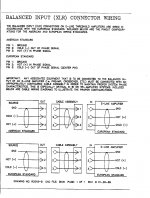
Found this US & European XLR connector wiring from Threshold service manual:
For someone with a "first course" in general electronics, they know exactly what is meant by "gnd" - the chassis, the signal ground on the PCB, or whatever, as "it doesn't matter because they're all connected together." But as we've discussed in this thread, it DOES matter.I think the term "gnd" is confusing.
Should all these connections be labeled "chassis"?
One can only presume the pin 1 on each chassis is connected to an appropriate place. This diagram is just to show the wiring of the cables, anyway.
The page is dated "1-26-89." It shows the US standard as Pin 1 being the "cold" or out of phase signal. I've known of the US "Pin 1 hot" standard since the late '90's, so either the standard changed within a ten-year period, or that page is based on an older US standard.
I've sometimes wondered if I should have an AES membership so I could search through back issues of its Journal so I can answer such "important" questions as when the pin 2 hot standard was introduced.
Found this US & European XLR connector wiring from Threshold service manual:
That is great from a historical perspective, but the AES abandoned the unique US configuration in a 1990 revision to it's standard (AES-014) that dates back to the practice of Ampex's adoption of the XLR connector in 1950. It should only be necessary for products made in the USA prior to 1990, and even then, the AES made the revision based on a poll of it's US member manufacturers, the majority of whom had been using the International Standard for some time.
The AES adopted the International Standard for microphones in 1975. The US motion picture industry created a new standard in 1986 reflecting industry practice with pin 2 hot.
Everything these days should be wired pin 2 hot.
When equipment wired to differing standards are interconnected with non-crossover cables, the signal phase is reversed and the shield is unaffected. The current standard worldwide including the US is pin 1 shield, pin 2 signal hot and Pin 3 signal return; the old AES was pin 1 shield, pin 2 signal return and pin 3 signal hot.
One can only presume the pin 1 on each chassis is connected to an appropriate place. This diagram is just to show the wiring of the cables, anyway.
The page is dated "1-26-89." It shows the US standard as Pin 1 being the "cold" or out of phase signal. I've known of the US "Pin 1 hot" standard since the late '90's, so either the standard changed within a ten-year period, or that page is based on an older US standard.
I don't really know of any gear that should be wired with pin 1 as anything but shield. Certainly it's not part of any standards I'm familiar with; AES-014 (sometime in the 1950's); IEC Publication 268, Part 12 (1975); Society of Motion Picture and Television Engineers: SMPTE Polarity for Analog Audio Magnetic Recording and Reproduction, RP-134-1986 (1986); European Broadcast Union :EBU Technical Recommendation R50-1988 "Conservation of the Polarity of Audio Signals in Radio and Television Production Installations".
Last edited:
That is great from a historical perspective, but the AES abandoned the unique US configuration in a 1990 revision to it's standard (AES-014) that dates back to the practice of Ampex's adoption of the XLR connector in 1950. It should only be necessary for products made in the USA prior to 1990, and even then, the AES made the revision based on a poll of it's US member manufacturers, the majority of whom had been using the International Standard for some time.
The AES adopted the International Standard for microphones in 1975. The US motion picture industry created a new standard in 1986 reflecting industry practice with pin 2 hot.
Everything these days should be wired pin 2 hot.
When equipment wired to differing standards are interconnected with non-crossover cables, the signal phase is reversed and the shield is unaffected. The current standard worldwide including the US is pin 1 shield, pin 2 signal hot and Pin 3 signal return; the old AES was pin 1 shield, pin 2 signal return and pin 3 signal hot.
I don't really know of any gear that should be wired with pin 1 as anything but shield. Certainly it's not part of any standards I'm familiar with; AES-014 (sometime in the 1950's); IEC Publication 268, Part 12 (1975); Society of Motion Picture and Television Engineers: SMPTE Polarity for Analog Audio Magnetic Recording and Reproduction, RP-134-1986 (1986); European Broadcast Union :EBU Technical Recommendation R50-1988 "Conservation of the Polarity of Audio Signals in Radio and Television Production Installations".
That hot/cold pin 2/3 is kind of a red herring. Does your gear _really_ pass the signal through with the positive peak still the positive peak?
I found an easy way to check that by placing a diode across the balanced input and use a scope to see which peak is clipped on the input and then check the output to verify.
Infinitely more important to not have interchannel phase errors - mis-wired connectors.
G²
- Status
- This old topic is closed. If you want to reopen this topic, contact a moderator using the "Report Post" button.
- Home
- Amplifiers
- Solid State
- Wiring a XLR plug