Hi,
I bought about this amp/tuner about a year ago now and have been really happy with it so far. However I knew right from the start the amp would benefit massively from an re-cap. Anyway I embarked on this about 3 weeks ago. It has been going very well. As you will see in the photo I've attached that I have replaced most of the old caps in the amplifier (all that remain are the odd ITT for which replacements haven't arrived). Anyway it was going well, at each stage I was powering up and running on my tester speakers and the sound was getting obviously better which each replacement.
Anyway, the point of this post... The other day I had a friend round and we were just doing some listening on the amp through my newly moded Goodmans Ministers (new peerless bass drivers). We decided to try inverting one of the tweeters to compare the sound. We preferred it so changed it on both. Anyway when we hooked up the speakers again we noticed that one channel was quieter. So I assumed that I was suffering a problem that I'd had before (where the wire to the positive side of one of the output caps had snapped at the terminal). Opened up the amp and had a look...
The wire was secure so we checked a few other things (turns out the din plug on the speaker was shorting internally). Anyway when we fired the amp up next - with the lid off as the amp's still a working progress - I saw the positiver terminal of the output cap spark to the chassis (The terminals are covered with sealing tape and a hole had worn through). Soooo I powered down, did a better job of insulating this and re-fired up. The moment I powered up a 100r resistor on the power amp board burst into flames. You can see the missing resistor in the top left of the board. Immediate power off and tears were shed.
So now I am left with trying to establish why this happened. I'm currently in the process of testing nearby components but don't really know where to start. Can anyone point me in the right direction as to what could have gone wrong to put that component under so much stress? I don't know much about transistors other than what they do, vaguely (don't know how to test them or anything) so don't know if one of them could be the problem... Any ideas please guys?!
in grateful anticipation, Josh
I bought about this amp/tuner about a year ago now and have been really happy with it so far. However I knew right from the start the amp would benefit massively from an re-cap. Anyway I embarked on this about 3 weeks ago. It has been going very well. As you will see in the photo I've attached that I have replaced most of the old caps in the amplifier (all that remain are the odd ITT
for which replacements haven't arrived). Anyway it was going well, at each stage I was powering up and running on my tester speakers and the sound was getting obviously better which each replacement.Anyway, the point of this post... The other day I had a friend round and we were just doing some listening on the amp through my newly moded Goodmans Ministers (new peerless bass drivers). We decided to try inverting one of the tweeters to compare the sound. We preferred it so changed it on both. Anyway when we hooked up the speakers again we noticed that one channel was quieter. So I assumed that I was suffering a problem that I'd had before (where the wire to the positive side of one of the output caps had snapped at the terminal). Opened up the amp and had a look...
The wire was secure so we checked a few other things (turns out the din plug on the speaker was shorting internally). Anyway when we fired the amp up next - with the lid off as the amp's still a working progress - I saw the positiver terminal of the output cap spark to the chassis (The terminals are covered with sealing tape and a hole had worn through). Soooo I powered down, did a better job of insulating this and re-fired up. The moment I powered up a 100r resistor on the power amp board burst into flames. You can see the missing resistor in the top left of the board. Immediate power off and tears were shed.
So now I am left with trying to establish why this happened. I'm currently in the process of testing nearby components but don't really know where to start. Can anyone point me in the right direction as to what could have gone wrong to put that component under so much stress? I don't know much about transistors other than what they do, vaguely (don't know how to test them or anything) so don't know if one of them could be the problem... Any ideas please guys?!
An externally hosted image should be here but it was not working when we last tested it.
in grateful anticipation, Josh
It's certain to be blown semiconductors (transistors)... maybe including the output devices which are mounted off the board.
If you don't know how to do basic tests on transistors I would perhaps google that and read up on it")
If you could post a circuit we could tell you what to measure...
If you don't know how to do basic tests on transistors I would perhaps google that and read up on it
If you could post a circuit we could tell you what to measure...
Hi Mooly,
Thanks for the help! I'll have a look at testing semiconductors...
Here's the schematic in the mean time!
http://img220.imageshack.us/img220/21/ampj.gif
Cheers, Josh
Thanks for the help! I'll have a look at testing semiconductors...
Here's the schematic in the mean time!
http://img220.imageshack.us/img220/21/ampj.gif
Cheers, Josh
Thanks for the circuit...
just one mad thought... if a wire to the output transistors broke (with keep moving the PCB) then that could cause the problem you have.
----------------------------------------------------------------------------------------------------------
I can virtually guarantee that replacing the driver transistors and outputs (if they are short) will fix it together with the 100 ohm, but it's nice to fix stuff properly.
With the amp OFF
You need to confirm that the two 0.47 ohm resistors are OK.
Next measure the output transistors on a "diode check" range on your meter. If they have failed it is almost certainly from Collector to Emitter.
Do the same for the driver transistors... I can't clearly make the ref numbers out, looks like 623 and 624. It the "2N" transistors anyway.
These are what to check. The transistors are all obsolete types but that's no problem at all. The BF258 (that's a video output transistor from the very early solid state bw/colour TV days) is probably OK.
When you replace any parts for this repair use a "bulb tester" which is a 100 watt filament bulb in series with the mains supply to the amp. It can save blowing output transistors if there is a fault.
Need to know exactly what has failed however. It's also possible but unlikely that the two ITT44 diodes have been damaged and also the 100 ohm preset.
For the cost of the parts tbh I would just replace the lot in both channels but it's educational to do it properly.
Attachments
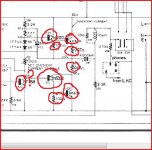
I checked all the components that you suggested, testing the transistors using the method shown for bi-polar's on this site... (anything not reading out at more or less what they said it should has been written off)
Testing semiconductors with analog and digital multimeters
I have put red rings around the damaged components, green rings round the tested and passed components. The blue rings signify that I was about to test the components and then my soldering iron stopped working... (ARGH!) but I strongly suspect, looking around the BF258 that it will also be knackered! I found that the 0.47ohm resistor that I passed came out at 8ohm, but I tested the two on the other side and found they also read out at 8ohm. I've put this down to the armstrong "rolling development" policy.
I will probably test some components further back the circuitry as well before I fire it up again, just in case the initial fault came from further back...
So now comes the lengthy process of finding replacements! Thankyou so much for the all guidance!
Testing semiconductors with analog and digital multimeters
I have put red rings around the damaged components, green rings round the tested and passed components. The blue rings signify that I was about to test the components and then my soldering iron stopped working... (ARGH!) but I strongly suspect, looking around the BF258 that it will also be knackered! I found that the 0.47ohm resistor that I passed came out at 8ohm, but I tested the two on the other side and found they also read out at 8ohm. I've put this down to the armstrong "rolling development" policy.
An externally hosted image should be here but it was not working when we last tested it.
I will probably test some components further back the circuitry as well before I fire it up again, just in case the initial fault came from further back...
So now comes the lengthy process of finding replacements! Thankyou so much for the all guidance!
Last edited:
I'll put some suggestions for parts down.
The 0.47 ohms... hmmm. They won't be 8 ohm for an "emitter" resistor. 0.47 is about as high as can be used for various reasons. Make sure your meter reads 0.00 when the leads are shorted together.
I think the best option is to rebuild both channels and keep them the same. It's a dead easy repair (famous last words) as long as you are methodical. I must look up the output devices to see what package they are in. Probably T03 at a guess.
8 ohm doesnt sound right - were these tested out of circuit? I'd suspect your meter cannot read low values correctly otherwise. 0.47 ohms is a typical emitter resistor value in output stages.
BF258 you may have to find old stock. The 2N5320/2N5322 are still made by ST and Semelab, Digikey have them. The 40636 power transistors can be subbed with 2N3055's - in fact this is what the RCA datasheet I found lists for them.
Edit: on second thoughts the 2N3055 looks like it's out of spec for the rail voltage used. No matter - pretty much any TO-3 device would work well here. 2N3773 as PB2 states, or MJ15003.
Last edited:
The 2N3773's are a good choice, what I had in mind too. The drivers are problematic because of the package, the "old" T039/T05 style. If it were me I would fit flat pack MJE340 and MJE350 perhaps with a clip on heatsink. The BF258 is no problem and is replaced by a BF259.
All these are available from CPC which I often use.
The 0.47 ohms are replaced by these,
WELWYN|W21 0R47 JI|RESISTOR, WW 3W 5% 0R47 | CPC
The 100 ohms, you have to buy a hundred ! still cheap.
--|MCF 0.5W 100R|RESISTOR, 0.5W 5% 100R | CPC
Don't forget new insulating kits for the outputs,
--|MK3301/S|TRANSISTOR INSULATING KIT TO-3 | CPC
and clip on heatsinks, which CPC seem not to stock
AAVID THERMALLOY|PF730|HEAT SINK, TO-126, 34°C/W | Farnell United Kingdom
Edit... as CPC is owned by Farnell perhaps use Farnell instead.
Last edited:
I'll put some suggestions for parts down.
The 0.47 ohms... hmmm. They won't be 8 ohm for an "emitter" resistor. 0.47 is about as high as can be used for various reasons. Make sure your meter reads 0.00 when the leads are shorted together.
My bad, meant to write 0.8ohms.
I was going to wonder at those, but for a different reason. Does it not matter that I would be switching from germanium to silicon with them? I read somewhere that they behave differently and shouldn't really be used. Please excuse my ignorance if this is completely wrong?
Thanks again for everyone's ongoing support!
Thanks again for everyone's ongoing support!
I don't think any of those are Germanium, what makes you think so?
The output stage is undersized for handling a short circuit load, is there a fuse or anything in the supply lines? I'll let you look.
Edit: OK I looked 2.5A are there in the schematic - were the right ones in there?
The VAS needs a current limter also if you want it to survive a shorted output.
I'd add a 2.5A fuse in each supply line to each channel, and a current limiter on the VAS set for about 50 mA.
The drivers are listed here, note that they were listed at Digikey but they have zero stock so it would be a special order:
2N5320 pdf 2N5320 datasheet General Purpose N-P-N Silicon Power Transistor. 2.7485 Transistors Bipolar Silicon NPN Power Transistors American Microsemiconductor 2N5320 available at 2.7485. FREE UPS ground shipping or more.
I've not ordered from them, so comments are welcome here as to the quality. I would ask what manufacturers they have and if you can specify a particular one in your order.
BD139/140 would also be fine as drivers note of course the different package and use a small heat sink.
Last edited:
Someone probably increased them for driving 4 ohm loads - I would have tried 3A first and it is probably OK as long as you don't short the output or let it get too hot - better to go back to 2.5A if you can.
BF259 is fine as a replacement for the VAS as Mooly stated above.
BF259 is fine as a replacement for the VAS as Mooly stated above.
Last edited:
I have found components of the right specs for pretty much all I need for sale on Farnell, what do you guys think of Multicomp semi's? worth a punt?
I don't have experience with Multicomp but my gut feeling is look for something better.
- Status
- This old topic is closed. If you want to reopen this topic, contact a moderator using the "Report Post" button.
- Home
- Amplifiers
- Solid State
- Overhaul of an Armstrong 625 gone wrong! Please help me :)