Original RCA 5 digit homotaxial transistors have much more base resistance than any modern transistor, even a "2n3055". Some people in replacing find that a 10 ohm 1 watt resistor between each driver and output transistor base is required. I did that when putting NTE60 on my similar dynakit ST120, only because I wanted something cheap to go up in flames the next time the OT's blew up. Turns out it was the right thing to do.
Modern transistors have Ft of at least 4 mhz versus the x hundred kilohertz of the old 5 digit RCA transistors. When dynaco went to the TIP3055 over the RCA source, they put 50 pf disk capacitors from c to b of the driver transistors. I did that on my ST120 in accordance with the "TIP mod". I also updated the idle bias current circuits to act more like the armstrong, and with those fast output transistors and slowed slew rate the sound was equivalent between my ST120 and my ~$1000 Peavey CS800s amp.
In reliability terms, I wouldn't worry about the 5 digit RCA transistors, but I would the mica insulators under them. Update those whatever you do, with new mica or with silicon rubber if you find a source. The silicon rubber ones available to me don't come with the PVC ferrule preventing shorts, so I'm still buying mica insulator kits from farnell, the multicomp ones.
You may want to update one side with mj15003 (specs about the same as the NTE60 I used) and take a listen between the two sides. The highs might be crisper. I had no choice, my 5 digit RCA transistors were scrap. The Armstrong heat sinks are much more competent than the dynakit ones. Somebody did a simulation of leak delta 70 with 2n3055 versus TIP3055 (faster Ft) and found the distortion much lower with the newer faster transistors.
after transistor upgrade do a oscillation check with a scope if you have one. If not, I found oscillation in my mixer with an analog VOM with 2 VAC scale (simpson 260-XLPM). A capacitor in series with one lead on a VOM is required to keep DC voltages from showing up on the AC scale. For checking normal music, a .047 UF 600v capacitor is what I use. When AC is present without hearing any music, changing the capacitor to 390 pf proved it was oscillation. Music will not pass through 390 pf.
Your speaker return revision sounds appropriate to me. The St120 has the speaker return jack fed back to the power distribution point but I moved it over to the emitter resistor. I put a .51 ohm emitter resistor on the lower transistor which the ST120 didn't have. The armstrong has the .51 but on the collector instead of the emitter. Moving it c to e may improve stability, at least that would be more modern.
I think an 80 v power supply with modern high gain transistors (25 instead of 5) give the opportunity of much higher voltage peaks on classical music, like the cannon shot in 1812 overture. The heat sinks won't produce 200 W/ch for very long, but modern transistors should put out 40 v on occasional peaks. IMHO. See what you think of the sound difference on music with wide dynamic range. My SP2-XT speakers are fine with 53 v music, your speakers may vary. I normally listen with Vpp of 1.5 VAC, on soft passages.
Have fun.
Last edited:
Many thanks for the info, I will have a good read of that. I have an old but working 15Mhz scope so will check for distortion. My 625 has been repaired by Armstrong in 1989, the 40636's have different codes on one channel and the drivers have been changed for 2SB861/2SD1138, I have the repair bill from Armstrong to match. Is it worth changing these for TIP41C/TIP42C.
There is a single main smoothing cap for both channels and the pre-amp circuit, it also might be worth separating these out per per power amp channel and a 3rd rectification circuit for the pre amp power supply. With it being a 625 there is a fair amount of space in the case.
I've also noticed mine has 1000uF caps on the power amp board, I haven't traced these through yet but they appear to be the feedback caps, the schematic that is commonly available for the 621 has 220uF feedback caps.
2.2uF electrolytics are primarily used for the signal path caps, I have some nice Sanyo 3.3uF 50V bipolars which I will probably used in place of these. Given I only paid £8 plus postage for the amp, I am not strict about keeping it original, I'd like to make some sensible mods to improve performance and make sure it can last another 43 years.
The phono stage is a little noisy and the BC384L used only have a 4dB noise rating, I will probably change these for KSC1845. I'd also like to improve the regulator for the small signal circuits but I need to find a circuit that can regulate from 80V down to 45V, my usual LM317 tracking pre-reg circuit can't handle those kind of voltages and thats probably too high a working voltage for the Salas shunt reg to operate at a sensible power dissipation.
Last edited:
Do not move the main audio ground to the PSU.One thing I have noticed is that all four speaker returns go to the GND on the pre-amp power supply and not the main smoothing capacitor, which isn't ideal at all so I will probably change this when I am working on it.
The 2SB861 has a Cob of 30 pf and Vceo of 150. I presume the 2SD1138 is similar, I can't buy these. Those are quite competent, probably a lot faster slew rate than a TIP41/42C. If no SOA rating on 2sb/sd transistor worries you, put a little heat sink on the drivers. One of my ST120 channel had original 5 digit RCA TO5 drivers, the other some RCA SK generic TO220 transistors from 1985. I'm sure the TO5 ones were quite slow, but I didn't hear any difference between the channels not even on top octave solo piano. The big HF benefit seems to be faster output transistors than 200 khz. That audible performance is with my 20-14000 hz ears and the 54-14500 hz +-3db Peavey SP2-XT speakers. I use a real Steinway piano as reference for amp and speaker tests.
I changed my input caps to tantalum in 1985, which added bass and also added frying pan sizzle. They might have been rejects as sold by the local TV parts store. I changed to 4.7 uf 50 v ceramic caps in 2009 which was a great improvement. Lower voltage would lead to more non-linearity of the dielectric. Bipolar 50 v 3.3 uf electrolytic caps could be fine sounding but limited in life to ~ 20 years after you bought them. I detest replacing e-caps, I've had to do the dynaco ST70 4 times since 1970 and these 1964-68 organs I play have consumed a couple of hundred new e-caps so far. **** e-caps deteriorate sitting on the shelf, even.
I find the single 3300 uf mains cap of my unit gives quite loud sonic peaks on 1.5 Vpp base level music. I did replace all e-caps in 1985. I can't say the 3300 uf is much of a limiter for 20 millisecond or so of a drum hit. For long term high power the heat sinks and the SOA rating of the single transistor pair are much more of a limiter than the cap resevoir.
For the 45 v regulator I find a zener diode to the base of a PNP transistor to be quite competent. The armstrong diagram has it correct. I just built a 72 v regulator for the rail of my ST120 based on this with 5 TIP142 pass transistor in parallel with .39 emitter resistors. The dynaco PC14 voltage regulator was incompatible with use with a test light bulb on the mains.
For eliminating noise on phono, I'd start by changing any & all resistors over 100 kohms to metal film. This took a lot of hiss out of my dynaco tube amp and preamp. The cheap multicomp and vishay metal film ones from farnell seem to be fine in the noise dimension. Noise increases with resistance, so I didn't bother with the smaller values. Of course my dynaco has mil-spec paint carbon comp resistors that don't increase in value due to moisture incursion like cheaper ones. An armstrong I don't know what your resistor value stability after 45 years would be.
Finally, if the update will put out 40 v drum/cannon shot peaks on room level classical (wide dynamic range) music, you might want to check your speaker tweeter that it will withstand that much. I blew a couple of voice coil tweeters just with a tube ST70 over the years, no cause found. I have mush more faith in these liquid cooled titanium diaphragm tweeters that came in the Peavey SP2-XT's I bought in 2010. Some pro PA speakers put a voltage surge supressor across the tweeter after the crossover to protect it from overdrive.
Last edited:
Thanks for the info again, I'll go over it a couple of times before I am ready to start.
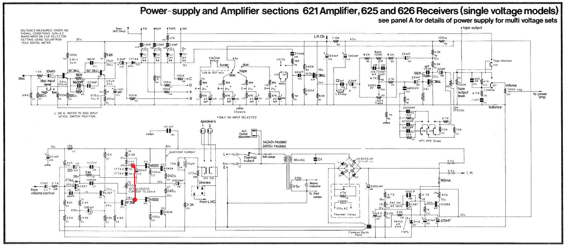
I got a copy of the original service data and a very large set of schematics (the full version of the schematic commonly available on the internet) with my receiver if anyone is interested in them.
I got a copy of the original service data and a very large set of schematics (the full version of the schematic commonly available on the internet) with my receiver if anyone is interested in them.
Did you see #48? That is the power amplifier schematic. If you want to see more details and the Tuner sections, you can see them all and read the descriptions and FAQs at Jim Lesurf's great website as well: The Armstrong 600 Series - tuner FAQ and diagrams.
- Status
- This old topic is closed. If you want to reopen this topic, contact a moderator using the "Report Post" button.
- Home
- Amplifiers
- Solid State
- Overhaul of an Armstrong 625 gone wrong! Please help me :)