Hi
I have the cyrus2 (issue06), serial number 204037c.
After cranking the volume just above 2, distortion set in on the Left channel. Right channel is functioning normally.
I open up the amp to check: no bloated caps on the AMP-L circuit. I spotted a green resistor R81 having brown discolouration on the cap body. Measures 122ohms (with amp OFF), schematic of R81 is 120ohm.
Is this the cause for the distortion?
Both poweramp 50v 10000uf cap looks alright.
What else can cause distortion?
Please help and give me your advise.
Thank you
CS law
I have the cyrus2 (issue06), serial number 204037c.
After cranking the volume just above 2, distortion set in on the Left channel. Right channel is functioning normally.
I open up the amp to check: no bloated caps on the AMP-L circuit. I spotted a green resistor R81 having brown discolouration on the cap body. Measures 122ohms (with amp OFF), schematic of R81 is 120ohm.
Is this the cause for the distortion?
An externally hosted image should be here but it was not working when we last tested it.
Both poweramp 50v 10000uf cap looks alright.
What else can cause distortion?
Please help and give me your advise.
Thank you
CS law
Hi Eric
Attach photo from another angle of R81
R81 is below the label AMP-L.
How to check the transistors. With power ON or OFF. And which transistor.
I have to admit i have little knowledge electronically, but am able to do component change.
CS Law
Attach photo from another angle of R81
An externally hosted image should be here but it was not working when we last tested it.
R81 is below the label AMP-L.
How to check the transistors. With power ON or OFF. And which transistor.
I have to admit i have little knowledge electronically, but am able to do component change.
CS Law
Ok, fault finding 101 for newbies.....
First off, service manual is here - Cyrus Cyrus 2 pwr amp Service Manual free download,schematics,datasheets,eeprom bins,pcb,repair info for test equipment and electronics ... in Acrobat Reader, right click>rotate clockwise might help.
First thing - you need a Multimeter that has a diode test position - even better if you have access to a Fluke 73/75/77.....if not, most cheapo meters have a diode symbol test position.
You are looking to test transistor junctions - with no power applied and a good transistor, B-E or B-C will test 0.6xx (or thereabouts) with correct probe polarity, and C-E will test open circuit.
If any junctions test short circuit or low value (isolate, desolder or remove the device to confirm) you have a rooted transistor.
Also test all resistors in the output stage and tell me what you find.
You give me the facts that I ask for and I will teach you how fix it.
Eric.
Measurement of the Left channel transistors Q45, Q43, Q39, Q41.
Q45: B-C 0.46, B-E 0.06, C-E ( value keeps increasing, i suppose its open circuit )
Q43: B-C 0.49, B-E 0.06, C-E ( value keeps increasing )
Q39: B-C 0.44, B-E 0.06. C-E ( value keeps increasing )
Q41: B-C 0.44, B-E 0.06, C-E ( value keeps increasing ).
Base is Left lead, Collector is middle lead, Emitter is Right lead ( info i got online ).
I cannot get proper ohm measurement from the resistors infront of the 4 output transistor. R91 /93 /87 /89, 95 measures about 0.6ohms each. ( base on schematic : should be 47ohm each, 120ohms ).
Are these measurement useful.
CS
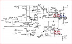
Is the circuit in the manual correct ? Look at Q24, there is no means of biasing the transistor. Q16 looks all wrong too.
Your measurements don't really tell much tbh and reading parts in circuit is no good. Also this doesn't really sound like a semiconductor failure, or not directly anyway.
Given limited test equipment I would measure and confirm the resistors in red here and remove for now the diodes in blue.
Measure the DC offset (voltage across the speaker terminals) and confirm it is zero.
Have you swapped speakers over to be sure it really is the amp at fault ?
Attachments
I cannot get proper ohm measurement from the resistors infront of the 4 output transistor. R91 /93 /87 /89, 95 measures about 0.6ohms each. ( base on schematic : should be 47ohm each, 120ohms ).
CS
The resistors I have highlighted are 0.47 ohms so you reading 0.6 ohms is OK (meter lead resistance added to 0.47)
R95 is a 0.22 ohm
My mistake: R 91/93/87/89 is R47 ( 0.47ohm ), R95 is R22 ( 0.22ohm ).
I hope i got it correct this round. Measurement is 0.6ohm and 0.3ohm respectively.
(
I hope i got it correct this round. Measurement is 0.6ohm and 0.3ohm respectively.
(
Measurement of the Left channel transistors Q45, Q43, Q39, Q41.
Q45: B-C 0.46, B-E 0.06, C-E ( value keeps increasing, i suppose its open circuit )
Q43: B-C 0.49, B-E 0.06, C-E ( value keeps increasing )
Q39: B-C 0.44, B-E 0.06. C-E ( value keeps increasing )
Q41: B-C 0.44, B-E 0.06, C-E ( value keeps increasing ).
Base is Left lead, Collector is middle lead, Emitter is Right lead ( info i got online ).
I cannot get proper ohm measurement from the resistors infront of the 4 output transistor. R91 /93 /87 /89, 95 measures about 0.6ohms each. ( base on schematic : should be 47ohm each, 120ohms ).
Are these measurement useful.
CS
The readings seem OK.
Have you swapped speakers over ? to be sure")
If the amp really is faulty next step in the absense of test gear has to be to carefully adjust the preset bias pot to confirm that the output stage passes current correctly. Disconnect speakers, volume on minimum.
You need to very carefully measure the volt drop across R95/96 and see if it can be taken up to say 120mv DC. That would correspond to just over 0.5 amp. If it can, return it back to the original value. If the either of the two diodes I mentioned were faulty that could cause distorted sound. The amp will run fine with them out to test.
Have you swapped speakers over ? to be sure
If the amp really is faulty next step in the absense of test gear has to be to carefully adjust the preset bias pot to confirm that the output stage passes current correctly. Disconnect speakers, volume on minimum.
You need to very carefully measure the volt drop across R95/96 and see if it can be taken up to say 120mv DC. That would correspond to just over 0.5 amp. If it can, return it back to the original value. If the either of the two diodes I mentioned were faulty that could cause distorted sound. The amp will run fine with them out to test.
Hmmm.... I'm pleased it's working of course
just make absolutely sure there are no dry/poor soldered joints around the output and driver transistors....... the resistor reading 122 ohm instead of 120 isn't the problem.... so something else has happened or "fixed itself".
It could even be a transistor failing open circuit which although unusual isn't unheard of!
I am interested to find out more about the cyrus 2.
From thread #11 "carefully adjust the preset bias pot to confirm that the output stage passes current correctly. Disconnect speakers, volume on minimum."
Tell me more on how to carry out this test.
1) Is this measurement done after changing transistor etc.
2) to check both channel output is equal / balance.
Are you referring to RV3 ( and RV2 for right channel ) seen in photo as the biasing pot.
The "bias pot" which is RV2 and RV3 (shown in the circuit post#6) allow the output transistors to pass (conduct) a small current in the absence of any audio signal. This is done to minimise crossover distortion in a push/pull class b (or ab) output stage.
A typical value of current would be around 20 to 100 milliamps. To measure this, the normal method is to just measure the volt drop across one of the emitter output resistors and calculate the current from ohms law.
----------------------------------------------------------------------------------------------------------
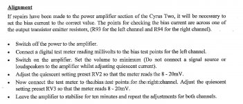
The service manual wording is confusing... it says use the above method using emitter resistors R93 and R94 for left and right channels. The circuit (post #6) shows one channel with two pairs of output transistors and R93/94 in the same channel... so without me having the unit in front of me it's confusing to give you exact advice... do you see
If your amp is as per the circuit in post #6 I would locate resistors marked R95 and R96 in each channel. Make sure your amp is like this and that these resistors are this value as fitted.
Measuring the voltage across this resistor adjust for around 10 millivolts which will be a current of around 45ma. The value will drift wildly as the output stage warms so keep rechecking and adjusting, doing the same for the other channel.
In practice a current of a couple of millamps and above renders the crossover distortion inaudible, go to high and the output stage runs too hot.
If the service manual procedure makes sense with the unit in front of you, and you can identify their test points then follow that, otherwise aim for around 45 milliamps measuring the voltage across a known resistor such as the 0.22 ohm.
Edit... this adjustment has no effect (in the terms you are thinking of) of giving different "channel balance" etc if set to different values or L/R were not equally balanced etc.
A typical value of current would be around 20 to 100 milliamps. To measure this, the normal method is to just measure the volt drop across one of the emitter output resistors and calculate the current from ohms law.
----------------------------------------------------------------------------------------------------------
The service manual wording is confusing... it says use the above method using emitter resistors R93 and R94 for left and right channels. The circuit (post #6) shows one channel with two pairs of output transistors and R93/94 in the same channel... so without me having the unit in front of me it's confusing to give you exact advice... do you see
If your amp is as per the circuit in post #6 I would locate resistors marked R95 and R96 in each channel. Make sure your amp is like this and that these resistors are this value as fitted.
Measuring the voltage across this resistor adjust for around 10 millivolts which will be a current of around 45ma. The value will drift wildly as the output stage warms so keep rechecking and adjusting, doing the same for the other channel.
In practice a current of a couple of millamps and above renders the crossover distortion inaudible, go to high and the output stage runs too hot.
If the service manual procedure makes sense with the unit in front of you, and you can identify their test points then follow that, otherwise aim for around 45 milliamps measuring the voltage across a known resistor such as the 0.22 ohm.
Edit... this adjustment has no effect (in the terms you are thinking of) of giving different "channel balance" etc if set to different values or L/R were not equally balanced etc.
Attachments
Last edited:
- Status
- This old topic is closed. If you want to reopen this topic, contact a moderator using the "Report Post" button.
- Home
- Amplifiers
- Solid State
- Cyrus2 amp Left channel distortion