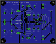
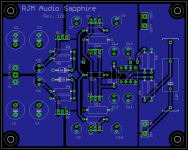
I've come up with a set of boards for a new headphone amplifier circuit that is a direct drop-in replacement for the Phonoclone 3 and VSPS300 boards, such that the power supply, chassis, and most of the connection hardware can be re-purposed. Or if you want both, it can be modular: it allows buying and building in bulk.
It's called the Sapphire.
The circuit replaces the X-reg with Zener-based series regulation, keeps a single op amp as the front end gain stage, and has a simple diamond buffer as the output stage.
The feedback loop is selectable: it can be taken from the output to keep the buffer in the loop (recommended if the buffer is biased in low-current class AB mode) or it can be routed directly from the op amp output, leaving the buffer running with no feedback (recommended if the buffer is biased heavily into class A).
Project is final beta stage. I'm still considering some last-minute adjustments:
- change values of certain passive components
- adjust size of input cap on board
- change transistor type
- add room for heatsinking the transistors
I will order a small batch of boards shortly, and they will be available at a special discount price to any "guinea pigs" who may with to participate.
/R
Attachments
Last edited:
@jaycee
What kind of power dissipation did you have for the transistors?
I'm still deciding what values to use myself. 10 mW class A output power into 16 ohms would seem like a reasonable target for the biasing. Much higher than that and things start to look like a mini space heater.
What kind of power dissipation did you have for the transistors?
I'm still deciding what values to use myself. 10 mW class A output power into 16 ohms would seem like a reasonable target for the biasing. Much higher than that and things start to look like a mini space heater.
@jaycee
What kind of power dissipation did you have for the transistors?
I'm still deciding what values to use myself. 10 mW class A output power into 16 ohms would seem like a reasonable target for the biasing. Much higher than that and things start to look like a mini space heater.
I love playing with headphone amplifiers and like to bias them high for round about 500 mW. All you need is a heat sink from an old PC microprocessor, disregard the fan.
With a little metal box around it could look aesthetically pleasing. Why do I high bias my headphone amp? Simply because I got a set of old Rogers LS3/5 sitting on my desk and 500 mW or even 1 watt class A is rather nice to have available.
Attachments
With an efficient driver stage and low voltage rails, 1 W class-A into 8 ohms can be obtained with a heat sink like you show there.
My circuit is not so efficient, as it's the classic LH0002 where the driver and output stages run at the same current. Also, the voltage rails I7m using are quite high. From the same heatsink (5-8W max with convection cooling) I'd be looking at about 15 mW into 16 ohms.
My circuit is not so efficient, as it's the classic LH0002 where the driver and output stages run at the same current. Also, the voltage rails I7m using are quite high. From the same heatsink (5-8W max with convection cooling) I'd be looking at about 15 mW into 16 ohms.
I've ordered 10 boards, so 4 pairs are available. Cost is $20 for a pair including shipping. Email or pm if interested.
I will provide support in the form of a custom BOM / instructions to each person who buys the boards, the values tailored to whatever application they propose: class A, class AB, high Z phones, low Z phones, power supply voltage, etc.
Parts cost for this project is pretty trivial, the capacitors are the bulk of the cost. $30-40 total, less power supply and chassis hardware. I will be placing an order with Mouser so if people want parts as well as the boards I can help out with this to a point.

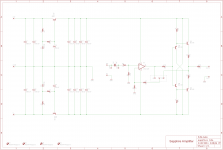
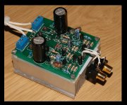
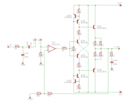
Here's my version (one channel obviously and without the power supply, which is nothing interesting)
It's biased at about 50mA i think. I use the heatsink from an old PC PSU for the output transistors. The MJE15032/3 transistors are probably overkill, but i didn't have any BD139/140 handy at the time. The Q103/104 transistors do get a bit warm but they're within spec.
My current breadboarded version has no gain - with the output of my PC it's not needed. I suppose you could get rid of the opamp, but the feedback gets the distortion down, and the OPA2134 opamp's FET input means low offset. Really, the coupling capacitor shown isn't needed.
Attachments
A very sensible circuit. Zobel on the output, 10 ohms after the op amp, and RC filter on the input. Current sources replacing the emitter resistors. All very nice and proper. Thanks for sharing that.
(in Agent Smith voice) The coupling capacitors are for your own ... protection...
They aren't needed until the one day when they save your voice coils from melting.
Wrapping the feedback loop around the output buffer reduces distortion but may also reduce stability. The question is which is the more important factor in play, something I don't have an answer for right now and for that reason the Sapphire proto boards are switchable. In principle, if the output buffer is heavily biased into class A so there is no crossover distortion then feedback should not be necessary.
12V bipolar supply is a lot of voltage for a headphone amplifier, and really not needed. Well, if you are running speakers from it is, but for low impedance headphones especially +/-5V is more than sufficient.
2 of the 4 proto boards are taken.
Fair note about the supplies, and I may indeed change it as I think I have a suitable 6-0-6 transformer someplace.
I tried the amp with the opamp feedback taken from the opamp output, and with the feedback taken after the buffer, and preferred the latter. I've had no stability issues except for when I was trying different opamps, some would oscillate as soon as I attached my oscilloscope probe to the output. The Zobel on the output cured that problem.
The L_VA and L_VB pins are to connect a potentiometer for volume control. The third pin of the pot would go to AGND, and you'd omit R102 - the input impedance would then be set by the pot. I did it this way so that the opamp and the attached device sees the same impedance no matter what the volume setting is.
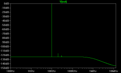
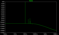
Here's the difference in output distortion at 10KHZ, 1V RMS. The first picture is without the buffer in the feedback loop, the second is with it. As you can see the distortion is much lower with, especially H3.
Choice is good though") At the moment I haven't made the PCB I designed (no time and my laser printer is broken)... but the version I made on my breadboard is running happily and being used every day with no problems.
At the moment I haven't made the PCB I designed (no time and my laser printer is broken)... but the version I made on my breadboard is running happily and being used every day with no problems.
Choice is good though
At the moment I haven't made the PCB I designed (no time and my laser printer is broken)... but the version I made on my breadboard is running happily and being used every day with no problems.Attachments
I'd be interested to know what load were you using when you made those measurements. Even without feedback the distortion is very low.
/R
PS The alpha BOM (not final, FYI only) is attached. There is a worksheet that lets you play around with some of the circuit parameters.
/R
PS The alpha BOM (not final, FYI only) is attached. There is a worksheet that lets you play around with some of the circuit parameters.
Attachments
It's a simulation, and it was a 32 ohm resistive load. This is the rough equivalent of my Beyerdynamic DT-231.
The reason I built this thing was because as of Windows 7, my onboard sound (which actually has a pretty good quality line out) no longer has a Headphone mode, and there is insufficient drive current to drive headphones otherwise.
Basically, it is a "lash up" made from parts I had kicking around. Sounds pretty good though It will eventually be connected to a dedicated DAC when I have the time/money to build one.
The reason I built this thing was because as of Windows 7, my onboard sound (which actually has a pretty good quality line out) no longer has a Headphone mode, and there is insufficient drive current to drive headphones otherwise.
Basically, it is a "lash up" made from parts I had kicking around. Sounds pretty good though
It will eventually be connected to a dedicated DAC when I have the time/money to build one.A simulation will usually underestimate the distortion of a push pull stage as the calculations use the same device model for each transistor (i.e. the parts are perfectly matched). Still, it's impressive.
I've been working on the BOM, bringing it out from alpha (clearly not for use) to beta (all checks fine, but not final). There are two configurations, one, for low impedance headphones, is based on 6 VAC secondaries while the other based on 12 VAC secondaries is optimised for 300 ohm 'phones.
Basically, if you are buying transformers specifically I'd suggest going with the 6 VAC option unless you use 300 ohm headphones. If you've got 12 VAC toroids already then use those, just understand that the available class A power into 16 ohms is quite low and it's probably a good idea to put the buffer in the feedback loop.
Both versions are intended to follow a 20 k volume control of some kind (you can get a nice 24 step attenuator on ebay quite cheaply), that is not shown in the circuit.
Attachments
Does this link work if you are not me?
Sapphire 6V Project at Mouser
NB: Fixed Mouser BOM import format in worksheet, part no. and qty. were reversed.
Sapphire 6V Project at Mouser
NB: Fixed Mouser BOM import format in worksheet, part no. and qty. were reversed.
Attachments
Last edited:
647-UKW1E102MPD can be substituted with 647-UFW1E102MPD or any general purpose 1000 uF 25V in 10mm dia. radial package (5 mm lead spacing)
647-UKW1E101MED can be substituted with 647-UFW1E101MED or any general purpose 100 uF 25V in 6.3mm dia. radial package (2.5 mm lead spacing)
This is noted in the latest version of the BOM, attached. Also fixed: the zener part no. for the 6 VAC version, which was incorrectly listed as a 12V type when it should have been 5.6V (copy-paste error).
P.S. I found some small heatsinks for the transistors, which are listed as optional in the BOM and qty. 0 by default. They can be used if you want to run a little more current through the current stage, and are probably a good idea for device dissipation above 0.25 W. I also found some neat little slip on ones, but they are not stocked by mouser unfortunately:
AAVID THERMALLOY 577500B00000G
Attachments
Last edited:
More searching. Found a nice case on ebay; get 'em while you can (shipping is a bit stiff tho~)
aluminum case
aluminum case
All the items for this project are now in transit, on their way to me.
The case linked to above has a 10 mm front faceplate. This is actually a negative in my book, because it means it's a total pain to drill out holes for the headphone jack etc. without a router.
Their are several sellers on ebay with pre-drilled chassis that even come with the power switch and IEC socket etc. included. for about $70-90 US including shipping, some steel ones for less. My only concern is that they are a fraction small. Fine if you are going to use an external power supply like the Phonoclone 3, but I'm personally planning on a one-box configuration this time.
Nice design RJM. I use something very similar in my 'X-Altra Mini One' preamp and can vouch for the sound quality, although I did not direct couple to the headphones like you did. Headphones definitely sound better when driven from a low source impedance.
BTW did you feel the 'quake in Kyoto? I was on the 24th floor in our Tokyo office and had to hang onto a pillar - it was almost impossibe to stand otherwise. LOL. Devastation up in Sendai though- my thoughts are with the people up there.
BTW did you feel the 'quake in Kyoto? I was on the 24th floor in our Tokyo office and had to hang onto a pillar - it was almost impossibe to stand otherwise. LOL. Devastation up in Sendai though- my thoughts are with the people up there.
Last edited:
- Status
- This old topic is closed. If you want to reopen this topic, contact a moderator using the "Report Post" button.
- Home
- Amplifiers
- Solid State
- Headphone amplifier drop-in replacement for Phonoclone 3 and VSPS300