Heat sinks
I have a table saw with carbide tip saw blade and as long as I feed it very, very and very slowly it cut beautifully. Anything else I used overheated the aluminum and it just puddled onto the teeth of the tool. I envy you guys for finding your fan type heat sinks. Damn!!!! And already TO-3 drilled. I have these hugh heat sinks where the fins run parallel lengthwise. 14 inches long, 6 inches wide and 2 inches deep. I was even thinking to cut across the fins to create spikes, put two together faces each other and place fan, push-pull at each each. I got these very cheap at a metal scrap yard. Kaplaars, I was wondering when you very going to run your tunnels verticle. As Superman says, "Up, up and away!"
I have a table saw with carbide tip saw blade and as long as I feed it very, very and very slowly it cut beautifully. Anything else I used overheated the aluminum and it just puddled onto the teeth of the tool. I envy you guys for finding your fan type heat sinks. Damn!!!! And already TO-3 drilled. I have these hugh heat sinks where the fins run parallel lengthwise. 14 inches long, 6 inches wide and 2 inches deep. I was even thinking to cut across the fins to create spikes, put two together faces each other and place fan, push-pull at each each. I got these very cheap at a metal scrap yard. Kaplaars, I was wondering when you very going to run your tunnels verticle. As Superman says, "Up, up and away!"
Attachments
Yes air cooled. But attaching a plank, to attached T0-3s, to a sealed rectangular conduit with a tube attached to a liquid circulator attached to an automobile heater core with a small fan then a tube back to the rectangular conduit. Just a thought, but that is available for computer CPUs on small smaller scale. The heater core may even not need a fan. There would be even liquid traveling--could add a dry sump canister of maybe a pint or so. I used this in my dry sump oil cooler unit in my race car. Crankshaft do not like oil sloshing in the engine's oil pan and most expensive--Porsche--use an oil radiator cooler. So they figured why take the oil storage out of the oil pan (away from the heat too) and put a canister mounted aside the inner engine compartment. Now, Kaplaars, or anyone. Would the output transistors NEED to be at atleast a optimal operating temperature?Hi David,
I have to say, in all honesty, that I do not share the observation Fix has made. I actually can't hear any difference when experimenting with bias values ranging from 100 mV and up. I begin to experience slight deteriation in sonic quality when I dial the bias far below 100 mV.
But I have to say, I don't listen music at very loud volumes. So the amp has not to deliver lots of power to drive my speakers. That is why, in my case, a lower bias will do just fine. When your speakers draw more power than your bias is set, and you exceed this value, then you can experience more distortion due to crossover distortion, but below it should not occur.
But cooling is very, very important. Lot's op people underestimate it. I for example did haha. That is why I want to add even bigger tunnel coolers because 1) I am bored haha, 2) because this way the fans have to displace even less air to get the same results and 3) because I offcourse want to go all the way ;-). After some evaluation I think it is after all beter to separate the tunnel coolers afterall, and place them upright just as fix did and the original KSA-100 has.
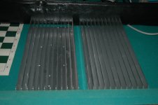
If I am correct the original KSA-100 uses tunnel coolers which are 12cm long. If I am not mistaken Fix is using tunnel coolers which are about the same length. Even then I think the KSA-100 runs pretty hot. So you will need probably more cooling. For my new plans I have bought these beauties (29cm long each, almost twice as heavy as the ones I use right now):
An externally hosted image should be here but it was not working when we last tested it.
I am thinking of cutting them through at about 18CM and place them upright. Does anybody has some experiencing with cutting aluminum profiles like these?
Liquid cooling would be very verry cool David! I would love to see that. Even better, it does not produce a lot of noise. I think for me that would be a little to expensive. I think I stick to aircooling.
Cutting aluminum
Kaplaars. I was very successful with cutting my aluminum sheets and bars up to 1 quarter inch .250. Like I said before, I used my table saw feeding it to the carbide tipped 10 inch saw blade. Even when I used my drill bench, the aluminum melted, but with the table saw, it sent very small chips out just like wood chips with no melting. You can cut one side, turn it over and cut the other side. If you have a table saw.Yes air cooled. But attaching a plank, to attached T0-3s, to a sealed rectangular conduit with a tube attached to a liquid circulator attached to an automobile heater core with a small fan then a tube back to the rectangular conduit. Just a thought, but that is available for computer CPUs on small smaller scale. The heater core may even not need a fan. There would be even liquid traveling--could add a dry sump canister of maybe a pint or so. I used this in my dry sump oil cooler unit in my race car. Crankshaft do not like oil sloshing in the engine's oil pan and most expensive--Porsche--use an oil radiator cooler. So they figured why take the oil storage out of the oil pan (away from the heat too) and put a canister mounted aside the inner engine compartment. Now, Kaplaars, or anyone. Would the output transistors NEED to be at atleast a optimal operating temperature?
Hi Friends!
I've been thinking about the overhaul of my KSA when spring break arrives. Main upgrade will be adding other tunnel coolers, together with bigger (14cm) fans. Now, my cooling tunnels have nice pre-drilled holes for 32 TO-3 devices. I will use one tunnel and cut it in halve. This would mean I could double the amount of output devices if I want to. Just for curiosity, would this be beneficial?
A benefit which comes with doubling the amount of output devices will be that every TO-3 device has to dissipate halve of the heat it is dissipating right now. If I am correct the total heat generated will be the same, because overall bias is still the same, thus also heat generated. But chances of getting out of SOA will be smaller, because the individual devices have to do less work.
A disadvantage could be that when doubling the amount TO-3 devices, chances of instability will rise because of internal ifferences between the devices (deviation in bias per device). Probably using 1 ohm emitter resistors will help to tackle this problem. Another problem could be oscillation.
What is wisdom? Am I forgetting something ? I like the sound right now, and I have always learned 'don't fix if it aint broken', but maybe improvement could be made") .
.
Also I am curious about optimal orientation of the coolers themself. What would be the best orientation? Fans on top and pushing air through the tunnels down or reversed thus pulling the air through the tunnels instead. An other orientation could be placing the fans beneath and pushing air upright through the tunnel, or go for pulling the air through instead? And offcourse I can use the push / pull principle like I am using right now, so one fan on top, and one fan beneath.
Sorry for the overflood of questions, but I am very curious.
I've been thinking about the overhaul of my KSA when spring break arrives. Main upgrade will be adding other tunnel coolers, together with bigger (14cm) fans. Now, my cooling tunnels have nice pre-drilled holes for 32 TO-3 devices. I will use one tunnel and cut it in halve. This would mean I could double the amount of output devices if I want to. Just for curiosity, would this be beneficial?
A benefit which comes with doubling the amount of output devices will be that every TO-3 device has to dissipate halve of the heat it is dissipating right now. If I am correct the total heat generated will be the same, because overall bias is still the same, thus also heat generated. But chances of getting out of SOA will be smaller, because the individual devices have to do less work.
A disadvantage could be that when doubling the amount TO-3 devices, chances of instability will rise because of internal ifferences between the devices (deviation in bias per device). Probably using 1 ohm emitter resistors will help to tackle this problem. Another problem could be oscillation.
What is wisdom? Am I forgetting something ? I like the sound right now, and I have always learned 'don't fix if it aint broken', but maybe improvement could be made
.Also I am curious about optimal orientation of the coolers themself. What would be the best orientation? Fans on top and pushing air through the tunnels down or reversed thus pulling the air through the tunnels instead. An other orientation could be placing the fans beneath and pushing air upright through the tunnel, or go for pulling the air through instead? And offcourse I can use the push / pull principle like I am using right now, so one fan on top, and one fan beneath.
Sorry for the overflood of questions, but I am very curious
.Devices
I know I am just a novice, but is it possible to run a POT to adjust resistance in series with the 1 Ohm emitter resistor to adjust internal differences between devices? Sorry about answering a question with a question.Hi Friends!
I've been thinking about the overhaul of my KSA when spring break arrives. Main upgrade will be adding other tunnel coolers, together with bigger (14cm) fans. Now, my cooling tunnels have nice pre-drilled holes for 32 TO-3 devices. I will use one tunnel and cut it in halve. This would mean I could double the amount of output devices if I want to. Just for curiosity, would this be beneficial?
A benefit which comes with doubling the amount of output devices will be that every TO-3 device has to dissipate halve of the heat it is dissipating right now. If I am correct the total heat generated will be the same, because overall bias is still the same, thus also heat generated. But chances of getting out of SOA will be smaller, because the individual devices have to do less work.
A disadvantage could be that when doubling the amount TO-3 devices, chances of instability will rise because of internal ifferences between the devices (deviation in bias per device). Probably using 1 ohm emitter resistors will help to tackle this problem. Another problem could be oscillation.
What is wisdom? Am I forgetting something ? I like the sound right now, and I have always learned 'don't fix if it aint broken', but maybe improvement could be made
Also I am curious about optimal orientation of the coolers themself. What would be the best orientation? Fans on top and pushing air through the tunnels down or reversed thus pulling the air through the tunnels instead. An other orientation could be placing the fans beneath and pushing air upright through the tunnel, or go for pulling the air through instead? And offcourse I can use the push / pull principle like I am using right now, so one fan on top, and one fan beneath.
Sorry for the overflood of questions, but I am very curious
I've said this in the other thread, so I'll be brief:
The easiest way to ensure good matching between the output transistors current is to use the largest reasonable value resistors that are matched. I used resistors that were nominally 5%, but better than that in practice, and I measured the current for all 6 pairs of output transistors which were not matched, save by being from the same lot.
Getting resistors that match to 1% is cheap and easy, and if you really want to do better than 1% you can get there pretty easily by buying more and measuring them with a decent meter. However, shooting for better than 5% matching is going to be more or less pointless unless you also make sure all the pcb tracks and solder joints in line are also similarly matched. It is also rendered pointless unless you can keep the thermal tracking across the entire heatsink equally perfect. Why? a 1c differential in the temperature of the transistors will induce a ~3% difference in the Vbe, ie the hotter transistor will try and steal more current at about 3% per degree C, the larger the emitter resistor, the larger it's induced voltage to counteract the drop in Vbe.
An important thing to note: The more output transistors you put in parallel the larger the emitter resistors need to be: Adjust the value of the resistor so the overall paralleled emitter resistance matches the original design. "But why?" I hear you ask, well the value of the output paralleled emitter resistors determines the bias voltage to achieve a given emitter current but it also sets the bias in the driver stage, ie lower bias voltage to get the output stage into class A reduces the current in the driver stage...If either half of the driver stage runs out of current, it's partner is still working to drive the output but as a pair they are no longer in class A and the amp will not sound like a Krell amp, even if the output stage never leaves class A.
For 6 pairs of output transistors we used 2ohm resistors, whose parallel resistance matches the ksa50's 2 output pairs 0.66 pretty well.
Ok, that was not brief...sorry
Stuart
Thinking about these issues with heat and emmiters and such.... At the CES in January this year, Vandersteen,s new amp coming out soon has liquid cooling, no emmiter resistors at all mounted on copper. Push,push instead of push pull Sankens. The biggest R core tranny I have ever seen sitting down on the bottom of the pyramid shaped enclosure with 6np2/6h30 tudes driving the whole thing.
Just refreshingly different and probably very nice sounding considering his track record.
Regards
David
Just refreshingly different and probably very nice sounding considering his track record.
Regards
David
Hi Guys,
Well, it seems I have a problem. When I turn the amp on without the output stage, for testing, in first few seconds everything looks fine, but then, the drivers (mje15032/33) and the bias transistor (mje15032) goes in smoke and they have shorted B-C-E. Output shows then 48V (rail voltage). Everything else seems to be ok. I checked everything and I don't have a clue. Bias trimmer potentiometer is at 1/10 of the value (5k). Any idea is welcomed.
Well, it seems I have a problem. When I turn the amp on without the output stage, for testing, in first few seconds everything looks fine, but then, the drivers (mje15032/33) and the bias transistor (mje15032) goes in smoke and they have shorted B-C-E. Output shows then 48V (rail voltage). Everything else seems to be ok. I checked everything and I don't have a clue. Bias trimmer potentiometer is at 1/10 of the value (5k). Any idea is welcomed.
The best replacement for Toshiba 2sa968/2sc2238 are Toshiba 2sa1837/2sc4793 after lengthy search on the net. Mouser price is $ 0.54, I can buy more for a pair transistors after amplification factor.
I have a question for Kaplaars.
Transformers use the company Amplimo produce any noise?
I used another application 2 transformers TALEMA intro had a noise when idling, bother me.
I have a question for Kaplaars.
Transformers use the company Amplimo produce any noise?
I used another application 2 transformers TALEMA intro had a noise when idling, bother me.
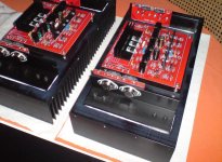
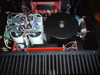
Well, I spent yesterday afternoon in listening and I must say that I'm impressed with the sound. Sound stage is huge. I think that the sound is even better than my first KSA50. Maybe, the reason is higher rail voltage. Bias is set at 325mV/0,5ohm. After two hours heatsinks are warm but not hot
Attachments
Sorry for my late response Guys, I’ve been very busy .
@Stuart: Thanks for your reply! I've got nice info from an other DIY-audio member about matching resistors, so that would be certainly doable. I've got milspec 1 ohm 1% resistors already. There seems a negligible deviation in resistance between them, so that should be a good thing. That is exactly my problem in the current setup, there is a slight temperature deviation between the different trannies. Although bias seems to divide very nice (about 10 mV difference max between the devices) I think using my new tunnel coolers will tackle this problem even better. Another advantage is that my new configuration has no longer 'live heatsinks', all the TO-3's will be isolated. Disadvantage is that heat transfer to the tunnel cooler will be slightly less.
Also thanks for the explanation about the emitter resistors! How could I forget that. So if I want to upgrade, it is necessary to use resistors with higher resistance. Will consider that!
@Neychi: Good that you tackled the problem! But that would be not good news for me because we are probably using the same devices. Are you sure the problem has been caused by the Polida devices? I have not experienced any problems thus far with them. Drove the KSA with a dummy to the max a few times, but it stays rock solid. Maybe I am lucky, but for how long? Have to say, from the 10 sets I've bought, one of the devices was faulty and thrown away before soldering it to the boards. Maybe there was a device which was faulty already before testing the KSA?
Nice pictures by the way, I like your amp very much!!!
@Vdavidov:
The Amplimo transformers are dead quiet, I realy can't hear them, even when I am 5 cm from them. They are only audible now and then when I connect my laser printer to mains. I think my laserprinter adds a nice DC component on the net. This causes the Amplimo's to hum. But that would probably be the case for every toroid. Have to check my printer soon
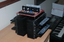
I've made some progress too. With a little heartache, I stripped my beloved KSA Like mentioned earlier I want to change thermal design. My main concern was cutting the tunnel cooler in two, so I would get two nice 14,5cm tunnel coolers. But this was actually more easy than I thought! Just the old fashined way, no electrical equipment involved:
Basic idea is this configuration:
Yuuup almost an exact copy of the original one, not very original from my side, but I think this is indeed the best configuration.
.@Stuart: Thanks for your reply! I've got nice info from an other DIY-audio member about matching resistors, so that would be certainly doable. I've got milspec 1 ohm 1% resistors already. There seems a negligible deviation in resistance between them, so that should be a good thing. That is exactly my problem in the current setup, there is a slight temperature deviation between the different trannies. Although bias seems to divide very nice (about 10 mV difference max between the devices) I think using my new tunnel coolers will tackle this problem even better. Another advantage is that my new configuration has no longer 'live heatsinks', all the TO-3's will be isolated. Disadvantage is that heat transfer to the tunnel cooler will be slightly less.
Also thanks for the explanation about the emitter resistors! How could I forget that. So if I want to upgrade, it is necessary to use resistors with higher resistance. Will consider that!
@Neychi: Good that you tackled the problem! But that would be not good news for me because we are probably using the same devices. Are you sure the problem has been caused by the Polida devices? I have not experienced any problems thus far with them. Drove the KSA with a dummy to the max a few times, but it stays rock solid. Maybe I am lucky, but for how long? Have to say, from the 10 sets I've bought, one of the devices was faulty and thrown away before soldering it to the boards. Maybe there was a device which was faulty already before testing the KSA?
Nice pictures by the way, I like your amp very much!!!
@Vdavidov:
The Amplimo transformers are dead quiet, I realy can't hear them, even when I am 5 cm from them. They are only audible now and then when I connect my laser printer to mains. I think my laserprinter adds a nice DC component on the net. This causes the Amplimo's to hum. But that would probably be the case for every toroid. Have to check my printer soon
I've made some progress too. With a little heartache, I stripped my beloved KSA
Like mentioned earlier I want to change thermal design. My main concern was cutting the tunnel cooler in two, so I would get two nice 14,5cm tunnel coolers. But this was actually more easy than I thought! Just the old fashined way, no electrical equipment involved:An externally hosted image should be here but it was not working when we last tested it.
Basic idea is this configuration:
An externally hosted image should be here but it was not working when we last tested it.
Yuuup almost an exact copy of the original one, not very original from my side, but I think this is indeed the best configuration.
Thanks Michael
Yes, I'm afraid so. Without changing anything else, only Toshibas, the problem is gone. I tested them before soldering and they seemed to be fine. Funny thing is that they still show correct readings. I burned another set of mje15032/33, because I didn't want to believe that the problem is in them. I put 2sa1011/2sc2344 for which I know they are original Sanyos and the amp works great. You've obviously had more luck.
Yes, I'm afraid so. Without changing anything else, only Toshibas, the problem is gone. I tested them before soldering and they seemed to be fine. Funny thing is that they still show correct readings. I burned another set of mje15032/33, because I didn't want to believe that the problem is in them. I put 2sa1011/2sc2344 for which I know they are original Sanyos and the amp works great. You've obviously had more luck.
Just a quick post:
Great thread, Great build !!!!
Congrats with the amp !!!!
I'm thinking of building another amp for myself.
Have most parts... Including Heatsinks and pcb's.
But this time I might build the fan-less version. If i can get hold of the right heatsinks.
Keep posting !!
Great thread, Great build !!!!
Congrats with the amp !!!!
I'm thinking of building another amp for myself.
Have most parts... Including Heatsinks and pcb's.
But this time I might build the fan-less version. If i can get hold of the right heatsinks.
Keep posting !!
Hi Everybody,
I have amplifiers Nad m3 and marantz Pm11s1 and my speakers sonus faber cremona m I like them but I want to drive my speakers with krell ksa 100
When this read this form. I decided to make my krell Thank you for this sharing.
My project not finish yet becauze some items missing. I bougt them from ebay. I am waiting. When they come I will finish. But now it is working perfect I am very happy.
My krell has big heatsink. Thus not heat to much. It heats max 43 c degree.
First a made a small heatsink but Its needs fan because It heats 65 c
First Ksa 100
Second Ksa 100
I have amplifiers Nad m3 and marantz Pm11s1 and my speakers sonus faber cremona m I like them but I want to drive my speakers with krell ksa 100
When this read this form. I decided to make my krell Thank you for this sharing.
My project not finish yet becauze some items missing. I bougt them from ebay. I am waiting. When they come I will finish. But now it is working perfect I am very happy.
My krell has big heatsink. Thus not heat to much. It heats max 43 c degree.
First a made a small heatsink but Its needs fan because It heats 65 c
First Ksa 100
An externally hosted image should be here but it was not working when we last tested it.
Second Ksa 100
An externally hosted image should be here but it was not working when we last tested it.
An externally hosted image should be here but it was not working when we last tested it.
An externally hosted image should be here but it was not working when we last tested it.
An externally hosted image should be here but it was not working when we last tested it.
An externally hosted image should be here but it was not working when we last tested it.
New heat sinks
Well, with the help from Stuart Easson, I think I have the right heat sinks. They are from ADCOM, don't remember the model number. They are square and will have to deal with that later. There is room for five output trans. All I have to do now is get the right heat sinks for MJE15s. I have smaller fin blocks, but I would have to stand the MJE15s straight up rather than "laying down on the job." Hey, maybe they will have "verticle sex." Also known as "dancing."
Well, with the help from Stuart Easson, I think I have the right heat sinks. They are from ADCOM, don't remember the model number. They are square and will have to deal with that later. There is room for five output trans. All I have to do now is get the right heat sinks for MJE15s. I have smaller fin blocks, but I would have to stand the MJE15s straight up rather than "laying down on the job." Hey, maybe they will have "verticle sex." Also known as "dancing."
Attachments
.JPG)
.JPG)
Heat Sinks
Yes, I am going to use two fans for push/pull effects.I think you will need a fan for these. They look too small. You could lower the bias level however and give it a go with enough room to add a fan later if necessary.
Regards
David
- Status
- This old topic is closed. If you want to reopen this topic, contact a moderator using the "Report Post" button.
- Home
- Amplifiers
- Solid State
- Stolen Trademark Amplifier from Jim's Audio on EBAY