Hi,
somebody already asked about this amp in the chipamp forum
http://www.diyaudio.com/forums/chip-amps/180861-has-any-one-tried-l20-350-watt-amp.html
but the thread was not moved or reopened, so I am asking basically the same question: Has anyone tried this particular mono amplifier or something similar?
What does it look like to you?
here is the ebay-item number to one of the auctions:
120646650832
it looks like this:
( ebay-seller: along1986090 )
(I am posting a picture of this because eBay auctions do not stay online very long and I often ran into threads with dead eBay links which is frustrating)
Any thoughts on this one? Usable with a good PSU and some cap replacements?
thanks
regards
meko
somebody already asked about this amp in the chipamp forum
http://www.diyaudio.com/forums/chip-amps/180861-has-any-one-tried-l20-350-watt-amp.html
but the thread was not moved or reopened, so I am asking basically the same question: Has anyone tried this particular mono amplifier or something similar?
What does it look like to you?
here is the ebay-item number to one of the auctions:
120646650832
it looks like this:
An externally hosted image should be here but it was not working when we last tested it.
( ebay-seller: along1986090 )
(I am posting a picture of this because eBay auctions do not stay online very long and I often ran into threads with dead eBay links which is frustrating)
Any thoughts on this one? Usable with a good PSU and some cap replacements?
thanks
regards
meko
Hmm, the amp seems not so popular 
alright... well, among many other amps he also sells some assembled "NAP 140" clone boards:
along1986090 items - Get great deals on 2pcs Classic NAP 140 CLONE mono power amplifier board items on eBay Stores!
I'd be using the supposedly good gigawork NAP140s, but they only deliver 70 watts into 8 Ohms.
I need a rather clean dual mono power amp set with approx. 100...200W into 8ohms per channel.
any suggestions?
thanks again
L20 project
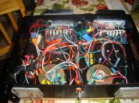
I just finished building an amp using the L20 boards with dual Plitron 40-0-40V @ 2.75 amps and 6 x 10K uF capacitors per channel in the power supply. I also used a soft start module and a speaker protection relay board for start-up. I had pipe dreams of using peltier devices which would allow me to get by with less heat sinks but my experiments with peltier devices were failures. So I have a thermal switch set to 85 degrees Celsius that will cut the AC if the temp by it reaches 85. So far the heat sinks have got quite warm but not too hot to touch. The maximum length of time I have had it on is 2 hours. I don't feel like tempting the fates by leaving it on.
How does it sound? So far quite good. It was built to replace an aging Yamaha M-70 that been in the shop 3 times in the last 2 years. My math says it was cheaper to build than repair. The L20 to my ears sounds slightly more detailed than the M-70 so I am a happy camper about this project although I should have had bigger heat sinks.
I am going to try to insert a picture of this project. My handy work is not so handy! I call this project the DB amp, DB stands for Dog's Breakfast in honour of ny chaotic wiring.
Attachments

Thank you for your use me to design the amplifier.
. If you have any questions, you can mail. ljm_ljm@foxmail.com
L20 in constant updates, to the stability of the better version, and better performance.
The current version is VER 9. L20 USES blue PCB materials. Blue is genuine.
Notice that there is some other color is probably pirated products.
. If you have any questions, you can mail. ljm_ljm@foxmail.com
L20 in constant updates, to the stability of the better version, and better performance.
The current version is VER 9. L20 USES blue PCB materials. Blue is genuine.
Notice that there is some other color is probably pirated products.
Hi,
Thanks,
i bought this one on ebay:
http://www.ebay.nl/itm/200723842622?ssPageName=STRK:MEWNX:IT&_trksid=p3984.m1439.l2648
best regards, and thanks for your help.
I probably will email you.
Are 2 of these:
Aluminum HEAT SINK FOR LM3886/TDA7293 Amplifier Board
professional QUALITY METAL Radiator 140*81*44mm,0.48kg
heavy enough?
I had pipe dreams of using peltier devices which would allow me to get by with less heat sinks but my experiments with peltier devices were failures.
You may have found this out while experimenting, but using peltiers would actually make more heat that needs to be dissipated.
-nelson
right capacitators in L20 V9?
Hi,
Just received the L20 KIT V9
The capacitators used are not the same uf or voltage
stated on the L20 board
100uF 80volt used on the board 150 uF 80 volt....
47uF 50volt used on the board 47 uF 63 volt.....
10uF 25volt used on the board 10 uF 50 volt...
470uF 16volt used on the board 470 uF 25 volt.....
Please tell me that if this is correct or not
best regards and thanks
marco
Hi,
I am looking at this amp PCB I got here - and I dont see where the Vcc+ is even used.
I also rather shockingly see that the output+ in the center of the board has nothing connected to it ?
Has anyone had one of these work ? I guess yes, but then again stuff just happens to not work with me ...
Anyway I will look in the pics and see what it looks like.
If Vcc+ isn't used, can I just run voltage to Vee- and ground ? Sorry for all the dumb questions. I am trying to learn this stuff.
Thanks.
Srinath.
I just finished building an amp using the L20 boards with dual Plitron 40-0-40V @ 2.75 amps and 6 x 10K uF capacitors per channel in the power supply. I also used a soft start module and a speaker protection relay board for start-up. I had pipe dreams of using peltier devices which would allow me to get by with less heat sinks but my experiments with peltier devices were failures. So I have a thermal switch set to 85 degrees Celsius that will cut the AC if the temp by it reaches 85. So far the heat sinks have got quite warm but not too hot to touch. The maximum length of time I have had it on is 2 hours. I don't feel like tempting the fates by leaving it on.
How does it sound? So far quite good. It was built to replace an aging Yamaha M-70 that been in the shop 3 times in the last 2 years. My math says it was cheaper to build than repair. The L20 to my ears sounds slightly more detailed than the M-70 so I am a happy camper about this project although I should have had bigger heat sinks.
I am going to try to insert a picture of this project. My handy work is not so handy! I call this project the DB amp, DB stands for Dog's Breakfast in honour of ny chaotic wiring.
From this pic I dont think anything is connected to Vcc+ and the red wire coming off the center of the board does bring sound huh.
Cool.
Srinath.
L20
I can assure you, the wires are connected. I succumbed to criticism and from a few helpful hints about grounding, I rewired the amp. Doesn't sound any different but it is a little easier to follow what goes where. I also installed better potentiometers for the level controls. I like this amp and will be building a third iteration soon. Hopefully I have learned something from the first two.
I can assure you, the wires are connected. I succumbed to criticism and from a few helpful hints about grounding, I rewired the amp. Doesn't sound any different but it is a little easier to follow what goes where. I also installed better potentiometers for the level controls. I like this amp and will be building a third iteration soon. Hopefully I have learned something from the first two.
Oh yes I see it, its etched on top too. The trace is on the top of the board.
OK so next stupid question.
I have a few of these lying around -
Cisco 34-0918-02 1300w Power Supply 6000/6500 | eBay
These have a 42v 25 amp output as well as 12v, and 5v outputs. They dont have negative taps though, so
A pair of those wired as a ladder would give me + and - 42 and the 5v would be right for a usb fan set I would think.
Is there a reason I shouldn't use that. As an added benifit I get a housing I can attach the wood and stuff to so my amp has a nice wood finish.
Thanks much guys.
Cool.
Srinath.
grounding
Ground is the center tap of all transformers you have connected, soldered, attached to the chassis..the commom point...the ground point... a central connection that sometimes is called "star ground".... there all ground wires goes, or all ground wires exits from this point... ground from amplifier pcboards goes there...ground from speaker black wire goes there, all transformers secondary center tap goes there..pre amplifier ground goes there.... potentiometer metalic cases goes there....wll ground joined together as a single wire...the same way you have in your car...all chassis and metalic parts are a big wire..the negative wire in the automobile..the ground wire.... this is the way we use to do.
+ and - must of coarse be connected at DC side of the PSU/rectifier board.
Speaker GND connects at center (gnd) PSU/rectifier board. also this connection goes to AMP L20 board GND connection. Audio In speaks for itself.
Make sure everything is Gounded as with the picture of the nice GREEN spaghetti (I LIKE THAT....) because it is well done!!
GOOD LUCK
L20 and grounding
Find here below a piece of text that is not written by me; but it's from a friend:
Ground is the center tap of all transformers you have connected, soldered, attached to the chassis..the commom point...the ground point... a central connection that sometimes is called "star ground".... there all ground wires goes, or all ground wires exits from this point... ground from amplifier pcboards goes there...ground from speaker black wire goes there, all transformers secondary center tap goes there..pre amplifier ground goes there.... potentiometer metalic cases goes there....wll ground joined together as a single wire...the same way you have in your car...all chassis and metalic parts are a big wire..the negative wire in the automobile..the ground wire.... this is the way we use to do.
I believe that grounding/safety is the basis....good sound comes next.
I'll make sure its ground well.
See that is also why I prefer to use a readymade power supply. Its already in a chassis, and has all the needed protection for safe operation. And it has lived in a computer for years.
So I am trying to get a +42 and a -42 volt from 2 powersupplies that only have 0 and 42Vdc. Is it possible to do that ?
Thanks.
Srinath.
OK google served this up: I think this I have seen but I plan to do this.
Thanks.
Srinath.
Whether you have two single channel DC power supplies or a triple output power supply, you can do the following to get the positive and negative voltage outputs.
1. Connect the two channels/supplies in a series configuration. Meaning, connect one of the power supplies' (A) negative terminal to the positive terminal of the second power supply (B). This will be the reference and you may also connect this to ground or chassis ground.
2. Now, power supply A will have an open port with the positive (+) terminal while power supply B will have negative (-).
3. To get positive voltage with reference to ground, just connect between the connection of the series configuration of A and B and the positive (+) terminal on power supply A. Likewise, to get negative voltage with reference to ground, connect between connection of the series configuration and the negative (-) terminal on power supply B.
4. The setup should look like the diagram below. Now, you have both a positive voltage output and a negative voltage output.
An externally hosted image should be here but it was not working when we last tested it.
2 x mono= stereo
i would use 1 transformator per channel.....the psu rectifier..........Amplifier board.....speaker protect board + soft start etc...
my choice; 2x mono is a cleaner sound. i you destroy 1 transformator you can still build the system.....safer option i guess. good luck
i would use 1 transformator per channel.....the psu rectifier..........Amplifier board.....speaker protect board + soft start etc...
my choice; 2x mono is a cleaner sound. i you destroy 1 transformator you can still build the system.....safer option i guess. good luck
- Status
- This old topic is closed. If you want to reopen this topic, contact a moderator using the "Report Post" button.
- Home
- Amplifiers
- Solid State
- ebay amp L20 power amplifier