Hi
I'm sure that many members of this forum will be familiar with D. Selfs writing, in particular the audio power amplifier design handbook. I finally managed to finish a paper with a couple of complementing and contrasting thoughts on the 5th edition of this classic. I hope you enjoy reading it and appreciate further conversation on the topics covered!
audio_power_amp_design_comments.pdf
Samuel
Hi
I'm sure that many members of this forum will be familiar with D. Selfs writing, in particular the audio power amplifier design handbook. I finally managed to finish a paper with a couple of complementing and contrasting thoughts on the 5th edition of this classic. I hope you enjoy reading it and appreciate further conversation on the topics covered!
audio_power_amp_design_comments.pdf
Samuel
Hi Samuel,
Thanks for doing this. I'll look forward to reading your comments.
Cheers,
Bob
Thanks Samuel, that's an heroic effort! ")
Here's my 2 cents about audio amplifier design books.
What I find lacking in many books about power amplifiers is novel ways of reducing distortion, many just focus on the same mechanisms that have been attributed to being at the root cause of amplifier distortion for the past three decades. The same I see happening here on DIYaudio, the same designs get rehashed over and over again.
In the meantime the folks that design opamps haven't been twiddling their thumbs. Many modern opamps use novel topologies that would be applicable to power amplifiers too, so why not borrow some good ideas from them?
You'll find that among the solutions employed there you'll find key ingredients which can significantly improve the performance of classic topologies. Ingredients which I can't seem to find in many of the books about power amplifier design (this includes Douglas's and Bob's).
Just for the fun of it have a look at the Miller topology. In its basic form it has a few issues, but these can be overcome. Basically there's four major obstacles we need to tackle:
1) PSRR: with Ahuja compensation the PSRR can be raised to >110dB with ease.
2) Slew rate: use degeneration to up the slewrate and prevent it being directly coupled to the GBW.
3) Non linear capacitance parallel to Miller C: simplest fix is to cascode the current junction.
4) Non linear impedance at the input: use a bootstrapped cascode or a folded cascode.
These are all pretty common ingredients in opamp design, but especially bootstrapping and cascoding seem to be heralded as detrimental to an amplifier's sonic performance. As such this speaks volumes about the folks that seem to qualify these as such.
Regardless, it would be nice to see some of these approaches applied to power amplifiers as well, or at least discussed in amplifier design literature.
/steps off soapbox
Cheers,
Sander.
it is hard to be "systematic" when exploring even simple circuit topology alternatives
"design space" is multidimensional and not "simply connected" nor is there any unique global optimum - "stage by stage" optimization may ignore some interactions, "theoretically better" changes in one stage may be totally masked by other stage's limitations leading you to discard an improvement that would be valuable in a more globally oriented optimiztion - or it may remain totally moot with other stage's unavoidable limitations
as an example of rapidly increasing "dimensionallity"
the "enhanced Beta" VAS - should it viewed as a composite transistor? and then do you need to compare all other known 2 transistor composites that can substitute for a single Q: CPF, Cascode, super pair
then you can go to 3 transistor composites - cascode the "Darlington" beta enhanced circuit... and you can see some of the topological complexity you can get into in Hawksford's Slope Distortion paper - what about CFP for any or all of the Q in each version?
how about VAS Q degeneration, with the input buffer - do the combined linearizing, gain increases change the VAS Q type analysis?
(Cherry shows VAS Q emitter resistor as valuable for stability wihtout VAS linearity cost - I really don't understand Self's insistance the the R is "not local negative feedback, only for current limiting")
I'm a little frustrated by the near complete lack of circuit theory based analysis - I like what Dr Cherry has done over his many articles in JAES but it is hard to penetrate - there should be a possible intermediate level of analysis
Cherry's ""Estimates of Nonlinear Distortion in Feedback Amplifiers" paper seems to be overlooked
maybe Middlebrook's "low entropy" equations?
the VAS stage analysis may benefit from even a simple circuit theory model that lets you more readily weigh topology change impacts
Last edited:
Thanks Samuel, that's an heroic effort!
Here's my 2 cents about audio amplifier design books.
What I find lacking in many books about power amplifiers is novel ways of reducing distortion, many just focus on the same mechanisms that have been attributed to being at the root cause of amplifier distortion for the past three decades. The same I see happening here on DIYaudio, the same designs get rehashed over and over again.
In the meantime the folks that design opamps haven't been twiddling their thumbs. Many modern opamps use novel topologies that would be applicable to power amplifiers too, so why not borrow some good ideas from them?
You'll find that among the solutions employed there you'll find key ingredients which can significantly improve the performance of classic topologies. Ingredients which I can't seem to find in many of the books about power amplifier design (this includes Douglas's and Bob's).
Just for the fun of it have a look at the Miller topology. In its basic form it has a few issues, but these can be overcome. Basically there's four major obstacles we need to tackle:
1) PSRR: with Ahuja compensation the PSRR can be raised to >110dB with ease.
2) Slew rate: use degeneration to up the slewrate and prevent it being directly coupled to the GBW.
3) Non linear capacitance parallel to Miller C: simplest fix is to cascode the current junction.
4) Non linear impedance at the input: use a bootstrapped cascode or a folded cascode.
These are all pretty common ingredients in opamp design, but especially bootstrapping and cascoding seem to be heralded as detrimental to an amplifier's sonic performance. As such this speaks volumes about the folks that seem to qualify these as such.
Regardless, it would be nice to see some of these approaches applied to power amplifiers as well, or at least discussed in amplifier design literature.
/steps off soapbox
Cheers,
Sander.
Hi Sander,
These are good points, but I believe you must have missed them somehow when you read my book.
Although I am not familiar with "Ahuja compensation", I do discuss PSRR issues with Miller compensation that results from one end of the capacitor being referenced to the rail while the other is referenced to signal ground, and mention compensation approaches that avoid this, such as what I call Miller Input Compensation. This is what I used in my MOSFET power amplifier that employed error correction published in 1984.
Of course, my book also prominently covers Hawksford Error Correction (HEC).
The second issue, that of using emitter degeneration to increase slew rate, is also covered extensively in several places in my book. I also discuss the fact that the use of Miller Input Compensation frees the amplifier to have very large slew rate virtually independent of compensation. When used in my MOSFET amplifier, that small 50W amplifier achieved a slew rate of 300 V/us.
The third issue, that of nonlinear collector-base capacitance in parallel with the Miller capacitor, is also covered in my book as a potential problem with simple Miller compensation. I show that the elimination of its effect is accomplished by placing an emitter follower in front of the VAS transistor (sometimes referred to as a Darlington VAS, but not in the Darlington sense where both collectors are tied together).
The fourth issue, using a bootstrapped (or "driven") cascode to reduce distortion at the input stage is also covered in my book in a couple of places.
In fairness to Doug, I think he has covered some of these as well.
I do not recall seeing where anyone asserted that cascoding was detrimental to the sound.
Cheers,
Bob
Thanks Bob,
Reading your reply I realize I should've ended mine mentioning that it would be nice to see a comprehensive writeup encompassing a lot of the novel approaches into design examples. It might even be worthwhile to set a few design requirements for an amplifier and work through a complete design from the ground up, describing the design choices, motivate them and finish off with a well rounded design that meets all the design requirements. This also gives folks that do not have design experience a guideline to work from.
I have read parts of your book and Douglas's latest, but although both look to be excellent writeups, most of the design examples or methods to reduce distortion (HEC for example) are decades old and you both seem to be using the same approach. Which is fine, ultimately it is the end result that counts, however methods such as putting an emitter follower in front of the Miller transistor obviously are getting a little long in the teeth.
That obviously doesn't render them ineffective, but modern opamps (for example the OPA1632 and the National LME49xxx series) employ novel methods that are both interesting and worthwhile to investigate. I'm convinced that creating interest and understanding for these novel approaches on amplifier design will yield new insights into distortion mechanisms and new ways to combat distortion and will motivate designers to try these in their own designs.
As for cascoding and bootstrapping, I've seen quite a few topics here and on other forums that refer to anything but the minimum required number of transistors to build an amplifier as detrimental to its sound quality. As a result folks often refer back to designs which are reminescent of '60s amplifiers as the pinnacle in amplifier design.
Either way, I appreciate your reply, I just wanted to give some feedback from the perspective of the reader. I however realize that what I find interesting and would like to read more about might not be the same for other people.
Cheers,
Sander.
That obviously doesn't render them ineffective, but modern opamps (for example the OPA1632 and the National LME49xxx series) employ novel methods that are both interesting and worthwhile to investigate. I'm convinced that creating interest and understanding for these novel approaches on amplifier design will yield new insights into distortion mechanisms and new ways to combat distortion and will motivate designers to try these in their own designs.
I believe that looking only at harmonic distortion wont bring us anywhere further. PPM THD is just a style exercise that has been done in books and on forums including this one, but does not bring any audible improvement over let's say .001%, as long as in BOTH cases high order harmonics are under the noisefloor.
Quality over quantity any time.
That's why sometimes simple designs sound better than very complex ones.
What is needed it to shift the focus to the quality of the distortion and to other distortion mechanisms that are ignored more often than not.
Also by opamp designers. I agree though, that a lot is to learn studying modern opamp circuits.
I use distortion for lack of a better word to describe all non-linear transfer functions in an amplifier's circuit that get added to the output signal and weren't in the original input circuit. I think that was clear from the exact piece of my reply you quoted?
Cheers,
Sander.
Thanks Bob,
That obviously doesn't render them ineffective, but modern opamps (for example the OPA1632 and the National LME49xxx series) employ novel methods that are both interesting and worthwhile to investigate. I'm convinced that creating interest and understanding for these novel approaches on amplifier design will yield new insights into distortion mechanisms and new ways to combat distortion and will motivate designers to try these in their own designs.
Cheers,
Sander.
Hi Sander,
Can you elaborate on some of the modern op amp techniques that you feel we have overlooked for use in audio power amplifiers? This might make for some good discussion.
Cheers,
Bob
Can you elaborate on some of the modern op amp techniques that you feel we have overlooked for use in audio power amplifiers? This might make for some good discussion.
Sure, here's a few on Ahuja compensation schemes that I found particularly interesting. I also have a number of (LT)spice simulations of actual working amplifiers using the points I mentioned in my previous replies that I simulated and built, but I'm not going to share these here publicly. I'd however be happy to discuss these with you in private.
AHUJA COMPENSATION CIRCUIT FOR OPERATIONAL AMPLIFIER
Ahuja compensation circuit with enhanced bandwidth
Ahuja compensation circuit for operational amplifier
P.s. please don't take my comments offensive, I hold you and Douglas in high regard and couldn't for the life of me write such a comprehensive book even if I wanted to.
Cheers,
Sander.
Thanks for your interest! I think it would be great if we could keep the discussion of this thread related to the topics covered in my paper. Everything else is just endless. Also I'm not sure how fair it is to make this thread a collection of "what I think is wrong with this and that book"; it's pretty easy to write a forum post, but to bring a bit of potential insight to the point where it can be objectively proven and published in printed form is a substantially more time consuming process, and we should honour that.
I'm nonetheless commenting a couple of responses.
1 and 2 are fully, and 4 at least partially covered by Self. For 3 I'm not sure what you mean by "current junction".
I'm not sure if Ahuja compensation is indeed a very "common ingredient" in opamp design, at least I'm not aware of many IC opamps which would not show the usual ~zero PSRR at unity loop gain. To make Ahuja compensation useful you need a ground port--which (non fully differential) IC opamp has this? Without a ground port compensation must be referenced to one or the other supply, in one or the other form.
From your reading I take it that you have more information on the inwards of these parts than I do--of course now I'm curious!
Just to put things into perspective: the amplifier from figure 50 of my paper has a THD+N of 0.000016% at 20 kHz/7.8 Vrms if we refer the (unloaded) measurement of figure 51 to a unity gain configuration, and that is mostly noise and generator/analyzer residual. LME49990 has 0.00003% at 20 kHz/3 Vrms, and this is mostly opamp distortion. So it doesn't look to me as if the IC world would be far ahead from relatively simple discrete design... Of course this is not a fully fair comparision (e.g. because of common-mode effects), but still.
I think what's at first needed is a better understanding of the topologies we already use. How many power amps and even preamps did I see where, for no good reason, noise was completely dominated by second stage, rather than input stage, noise (see section 3)? How many amplifier roughly similar to that of figure 56 were built with C1 connected to a supply rail rather than ground, completely waisting the potentially near-perfect PSRR?
Samuel
I'm nonetheless commenting a couple of responses.
Just for the fun of it have a look at the Miller topology. In its basic form it has a few issues, but these can be overcome. Basically there's four major obstacles we need to tackle:
1) PSRR: with Ahuja compensation the PSRR can be raised to >110dB with ease.
2) Slew rate: use degeneration to up the slewrate and prevent it being directly coupled to the GBW.
3) Non linear capacitance parallel to Miller C: simplest fix is to cascode the current junction.
4) Non linear impedance at the input: use a bootstrapped cascode or a folded cascode.
These are all pretty common ingredients in opamp design, but especially bootstrapping and cascoding seem to be heralded as detrimental to an amplifier's sonic performance. As such this speaks volumes about the folks that seem to qualify these as such.
Regardless, it would be nice to see some of these approaches applied to power amplifiers as well, or at least discussed in amplifier design literature.
1 and 2 are fully, and 4 at least partially covered by Self. For 3 I'm not sure what you mean by "current junction".
I'm not sure if Ahuja compensation is indeed a very "common ingredient" in opamp design, at least I'm not aware of many IC opamps which would not show the usual ~zero PSRR at unity loop gain. To make Ahuja compensation useful you need a ground port--which (non fully differential) IC opamp has this? Without a ground port compensation must be referenced to one or the other supply, in one or the other form.
That obviously doesn't render them ineffective, but modern opamps (for example the OPA1632 and the National LME49xxx series) employ novel methods that are both interesting and worthwhile to investigate.
From your reading I take it that you have more information on the inwards of these parts than I do--of course now I'm curious!
Just to put things into perspective: the amplifier from figure 50 of my paper has a THD+N of 0.000016% at 20 kHz/7.8 Vrms if we refer the (unloaded) measurement of figure 51 to a unity gain configuration, and that is mostly noise and generator/analyzer residual. LME49990 has 0.00003% at 20 kHz/3 Vrms, and this is mostly opamp distortion. So it doesn't look to me as if the IC world would be far ahead from relatively simple discrete design... Of course this is not a fully fair comparision (e.g. because of common-mode effects), but still.
I think what's at first needed is a better understanding of the topologies we already use. How many power amps and even preamps did I see where, for no good reason, noise was completely dominated by second stage, rather than input stage, noise (see section 3)? How many amplifier roughly similar to that of figure 56 were built with C1 connected to a supply rail rather than ground, completely waisting the potentially near-perfect PSRR?
Samuel
Thanks for your interest!
Well, you wrote an excellent paper, with some good insights, enough to peak anyone's interest that designs, or is interested in, amplifiers.
I think it would be great if we could keep the discussion of this thread related to the topics covered in my paper.
I'm sorry, you are of course correct, your objective was not to discuss Douglas's book, but rather your comments about the book.
For 3 I'm not sure what you mean by "current junction".
I meant cascoding, but reading back my post I find it could mean something else as well, sorry for the confusion.
I'm not sure if Ahuja compensation is indeed a very "common ingredient" in opamp design, at least I'm not aware of many IC opamps which would not show the usual ~zero PSRR at unity loop gain. To make Ahuja compensation useful you need a ground port--which (non fully differential) IC opamp has this? Without a ground port compensation must be referenced to one or the other supply, in one or the other form.
Correct. I'm not saying Ahuja is typically used in opamps, I'm just stating that that is one fix for the PSRR problem which yields excellent results, there's other more elaborate compensation schemes used in modern opamps. And yes, Ahuja needs an explicit reference, but as you already pointed out that reference doesn't need to be ground.
From your reading I take it that you have more information on the inwards of these parts than I do--of course now I'm curious!
You have email!
Just to put things into perspective: the amplifier from figure 50 of my paper has a THD+N of 0.000016% at 20 kHz/7.8 Vrms if we refer the (unloaded) measurement of figure 51 to a unity gain configuration, and that is mostly noise and generator/analyzer residual. LME49990 has 0.00003% at 20 kHz/3 Vrms, and this is mostly opamp distortion. So it doesn't look to me as if the IC world would be far ahead from relatively simple discrete design... Of course this is not a fully fair comparision (e.g. because of common-mode effects), but still.
I'd like to see some practical examples of that. I'm no stranger to seeing stellar THD results in the simulator, but translating them to the real world, with all the practical challenges you'll be faced with (layout, temperature variations, parasytics, etc.), is another story.
I think what's at first needed is a better understanding of the topologies we already use. How many power amps and even preamps did I see where, for no good reason, noise was completely dominated by second stage, rather than input stage, noise (see section 3)? How many amplifier roughly similar to that of figure 56 were built with C1 connected to a supply rail rather than ground, completely waisting the potentially near-perfect PSRR?
Makes perfect sense to me. What I think would certainly help is a more systematic approach to the design of an amplifier from the ground up covered in the literature. Documenting and weighing each design choice and available options and illustrating what motivates these design choices helps to better understand the underlaying issues and/or compromises.
Cheers,
Sander.
Hello Sander
Do think that the LM4562 uses Ahuja to get its PSSR performance.
Regards
Arthur
not physically possible - a "5 pin" op amp doesn't have a gnd reference terminal - looking at the datasheet plots the -PSRR pretty closely follows the differential gain curve
The best source for really understanding the issues is “A General Relationship Between Amplifier Parameters, And Its Application to PSRR Improvement” – a search should find the CiteSeerX page and you can grab the cached pdf for free
CiteSeerX — A General Relationship between Amplifier Parameters and its Application to PSRR Improvement
Hello Sander
Do think that the LM4562 uses Ahuja to get its PSSR performance.
Regards
Arthur
I'm pretty sure that's a bootstrapped (folded) cascode approach on the input stage, but I think most of the 'magic' is in the output stage as that's very well behaved, even in low impedance loads. It wouldn't surprise me if the topology isn't much different from the AD797 (see below datasheet, page 11).
http://www.analog.com/static/imported-files/data_sheets/AD797.pdf
Cheers,
Sander.
I'd like to see some practical examples of that. I'm no stranger to seeing stellar THD results in the simulator, but translating them to the real world, with all the practical challenges you'll be faced with (layout, temperature variations, parasytics, etc.), is another story.
I'm not sure I understand what you're saying. The measurements in my paper are what they claim to be--measurements, not theoretical results (i.e. simulations)...
Samuel
Hi Samuel,
I corresponded with you yesterday regarding the results of the topologies you suggested in your paper. If you don't mind I'll go ahead and post part of that correspondence here. As I mentioned I worked them into practical simulations, by doing some direct comparisons using the same set of stimuli (0.5Vpp 20kHz sine wave) and operating conditions for your Fig 50, Fig 52 and my own Ahuja compensated design and looked at THD@20kHz with a gain of ~22x into 22kOhm. As you can see there's about a 6dB reduction in THD between your (best score) Fig 52 and my design.
Also, how did you arrive at the THD+N scores you claim for Fig 50 and 52, what was the configuration and stimuli used? I'd like to see if I at least can reproduce these scores in the simulator.
Looking forward to your reply.
Cheers,
Sander.
Attachments
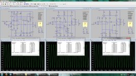
The amplifier from figure 52 was designed to show how sensitivity to VAS loading may be reduced at minimal parts count. It is not designed to have good common-mode distortion performance, which explains at least part of the distortion performance difference you observed. Unfortunately I can't read all the parts designators in the picture you posted; there are however many deviations from the parts I used so this possible will further detoriate distortion performance.
I suggest you subject your amplifier to the nonlinear VAS load test with the network from figure 45 as well--to make a meaningful comparison to my results (particularly the amplifier from figure 52) also add a 68 Ohm VAS emitter resistor to your amp which is anyway likely needed for current limiting. This test will be a good indicator how suitable your frontend is to actually drive a real-world power output stage.
To reproduce the measurements in my paper use an inverting configuration with noise gain of 22.
Samuel
- Status
- This old topic is closed. If you want to reopen this topic, contact a moderator using the "Report Post" button.
- Home
- Amplifiers
- Solid State
- Comments on Audio Power Amplifier Design Handbook by Douglas Self