Hi,
I am making a power dac, as part of my on going personal research in to sound quality. Purpose of, to achieve minimum of everything, signal path, active components, no feedback etc to try and hear the raw sound of "digital" so to speak.
basics:
wm8804
2x tda1543
ecc88 as I/V converter
shunt volume control
class a(b) bipolar darlington output buffer with dc servo
about 10W
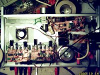
I have a prototype up and running and now sounding fairly together, am posting interesting observations for anyone interested:
first interesting shock was how much effect a normal electrolytic decoupling across my vbe multiplier had, changed to oscon much cleaner!
not sure if this has been done elsewhere, but inverted WS to one of the TDA1543 and the left right connections, this gives a sort of 2x oversampling with slight cost of 11uS delay, sounds happier like that.
all for now, hope to post more if any interest as i need to write up this project, but busy so not much time.
h
I am making a power dac, as part of my on going personal research in to sound quality. Purpose of, to achieve minimum of everything, signal path, active components, no feedback etc to try and hear the raw sound of "digital" so to speak.
basics:
wm8804
2x tda1543
ecc88 as I/V converter
shunt volume control
class a(b) bipolar darlington output buffer with dc servo
about 10W
I have a prototype up and running and now sounding fairly together, am posting interesting observations for anyone interested:
first interesting shock was how much effect a normal electrolytic decoupling across my vbe multiplier had, changed to oscon much cleaner!
not sure if this has been done elsewhere, but inverted WS to one of the TDA1543 and the left right connections, this gives a sort of 2x oversampling with slight cost of 11uS delay, sounds happier like that.
all for now, hope to post more if any interest as i need to write up this project, but busy so not much time.
h
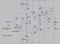
Yes you are right, it is not that much of a power dac... It is about getting the (normal) dac as near to the output stage as possible with hopefully the least number of the most transparent audio stages i.e. a triode and a class A buffer. I know a bit about switch mode psu, but not sure I would personaly try that approach ! I would always be tempted to have all the current sources running in to the bottom of a cascode, which is effectivly what I have got in my circuit.
h
h
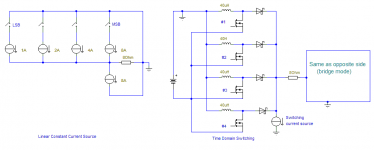
I ever make a power DAC once and yes only once using that time based switching, and only 8bit resolution 33KHz. It need at least 4 parallel switch to discharge inductor current to zero each cycle. It is become too complex, rejecting supply ripple with precise A*B circuitry, reducing Mosfet timing error, and many more.
Any way, what is your goal? more linearity or more power, from your circuit?
Any way, what is your goal? more linearity or more power, from your circuit?
The most transparent digital playback...?
Hi,
I know I am a noob to posting here, but I have been doing this stuff for 25+ years. and have a pretty good home made set up, that I can listen to almost anything (music) and it sounds good, anyway.
The Mrs has gone out and its daytime and I have been spending a few hours listening to this thing..... ****... yes it has a sound of its own, or maybe its my speakers, I need to test it on some other settings.
I need to make these and sell them to every record company, because they would never make a bad sounding CD again if they had to listen to it on this...wow.
got my Isely brothers super-hits, its your thing, great intro, loved it in the car for a couple of minutes, great for a pulsating exit of petrol station moments, but then it went down hill fro there on, and normally got spat out after. I totally know why now, what a mess, where as pull out an AAD loyd cole big snake, sounds delicious, (my CD collection is a bit inaccessible due to moving house and having free roaming small destructive hands at work).
Attempted description of sound, if possible: all constituent sounds are free of each other, they start and stop independently in there own space. some familiar CDs Duende, a man called Adam, man what were they thinking, gratuitous compression I had never noticed before, totally obvious now, it is like the recording is de-constructed.
so it goes. I have "integrated it now, it no longer needs 3 separate power plugs, so time to move on to some evaluation.
Attempted some measurements last night, not really conclusive. My Sound Technology 1700 has broken (haven't used it for 10 years), sniff, I am hoping it is just the oscillator, as I don't really need that bit.
I couldn't get Paraxis to work, But ARTA works ok (W7 64bit), Have access to a prism sound set up at college, but I like to work at home. At any recommendations for free software I could use to check this thing out on.
@ontoaba
Hi,
I love the recorded sound time machine/ travel, shut your eyes and you are some where else, some other time effect. I like to know how things work, I don't like bulshit myths that transistor amps sound bad because of crossover distortion, why do SETs sound nice etc etc, I want to know the truth!!!
Hi,
I know I am a noob to posting here, but I have been doing this stuff for 25+ years. and have a pretty good home made set up, that I can listen to almost anything (music) and it sounds good, anyway.
The Mrs has gone out and its daytime and I have been spending a few hours listening to this thing..... ****... yes it has a sound of its own, or maybe its my speakers, I need to test it on some other settings.
I need to make these and sell them to every record company, because they would never make a bad sounding CD again if they had to listen to it on this...wow.
got my Isely brothers super-hits, its your thing, great intro, loved it in the car for a couple of minutes, great for a pulsating exit of petrol station moments, but then it went down hill fro there on, and normally got spat out after. I totally know why now, what a mess, where as pull out an AAD loyd cole big snake, sounds delicious, (my CD collection is a bit inaccessible due to moving house and having free roaming small destructive hands at work).
Attempted description of sound, if possible: all constituent sounds are free of each other, they start and stop independently in there own space. some familiar CDs Duende, a man called Adam, man what were they thinking, gratuitous compression I had never noticed before, totally obvious now, it is like the recording is de-constructed.
so it goes. I have "integrated it now, it no longer needs 3 separate power plugs, so time to move on to some evaluation.
Attempted some measurements last night, not really conclusive. My Sound Technology 1700 has broken (haven't used it for 10 years), sniff, I am hoping it is just the oscillator, as I don't really need that bit.
I couldn't get Paraxis to work, But ARTA works ok (W7 64bit), Have access to a prism sound set up at college, but I like to work at home. At any recommendations for free software I could use to check this thing out on.
@ontoaba
Hi,
I love the recorded sound time machine/ travel, shut your eyes and you are some where else, some other time effect. I like to know how things work, I don't like bulshit myths that transistor amps sound bad because of crossover distortion, why do SETs sound nice etc etc, I want to know the truth!!!
Hi Ontoaba, Yes initially I used a transistor, Q5 on circuit above, with adjustment to base voltage, I had the digital circuit on the -ve rail. it was OK but I just don't quite trust tranies in this kind of roll with no feedback. have not conclusively proved to my self yet, but still.
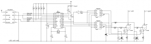
now have a set up "like" the one here, with the signal going to the cathode, RF style. used this circuit initially because it looked like it would do what I wanted it to do, No Over-Sampling DACs and tubes but it really doesn't work very well. so I have now just fixed bias. will post cct when I get one drawn.
I am a bit confused about the sound at the moment, because it is so different to anything else I have done. basically if you turn up the volume you just get more, louder is better, because you can hear more!
I need to do some more listening in other systems to get a proper opinion. I have done some measurement, and frequency response is flat, and distortion is 2nd -56dB, 3rd -39dB, relative to -4 dB fundamental IIRC @ 1k.
The -ve rail of the sounds tech has gone down, it doesn't look to complicated so hopefully can fix.
h
It is better to not modify your first success, until you built another. Sometimes our ears feel everything worse. And if you want to find "truth", use only your eyes to measuring sound quality will not help. Scope based(ARTA) measurement only help to show any voltage waveform based, not sound waves that we heard.
That probably hearing fatigue or something else, like bad situation that you feel.
I am sure, the pot did change speaker driving composition. If you need more power up 20W or more, may be I could help with my linearized emitter follower classAB that will do almost same with classA EF.
Any comparison of two or more amplifiers, are very helpful. Of course, you need to fix -ve first") .
.
That probably hearing fatigue or something else, like bad situation that you feel.
I am sure, the pot did change speaker driving composition. If you need more power up 20W or more, may be I could help with my linearized emitter follower classAB that will do almost same with classA EF.
Any comparison of two or more amplifiers, are very helpful. Of course, you need to fix -ve first
.
Last edited:
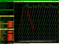
It seems that the distortion coming from the tubes not the output stages. The configuration added the tube current to DAC source current. The result is it more linear, but still distorted most at H3.
Hi, hbc, did that 470ohm and double TDA1543 is the best value or just placed there by calculation?
Hi, hbc, did that 470ohm and double TDA1543 is the best value or just placed there by calculation?
Attachments
Hi, h
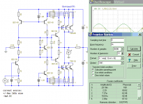
I am simulating bjt version replacing the tubes. It also has higher H3 distortion. This one is linearized EF in classB with 1/10 current gain of normal EF, ready for 50Watts with (modified)higher Vref of current sources.
The input should be in positive side, to get it the similar. May be just fine, it is only reversed loudspeaker polarity differences.
Attachments
Have been / am a bit ill at the moment, (writing this in bed!!) in occasional burst of energy have been able to progress a bit. Fixed sounds tech distortion analyser. A Tantalum cap added to help noise (wasn't me) had gone short.
Re not changing things and listening fatigue, yes I agree, there are many variables. I have been curious about these things and have some of the variable pinned down I feel. See:
http://www.artandmusic.netfirms.com/mysticalear/weird.html
note: this link doesn't work today, will try and fix when I have time, (sorry)
It is quite easy to put a transistor back in to the circuit, I also want de-construct the circuit quite soon and measure the different elements.
Anyway, have been able to make some measurements, and these come in a about 1%THD at full output of 10 Watts in to 8R. The ARTA does do measurement of distortion and all sorts of things, I am learning to love it more all the time.
http://www.fesb.hr/~mateljan/arta/
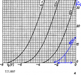
using the curves from mr klausmobile:
Tube Tester Files - 6N23P - 6H23P
Re not changing things and listening fatigue, yes I agree, there are many variables. I have been curious about these things and have some of the variable pinned down I feel. See:
http://www.artandmusic.netfirms.com/mysticalear/weird.html
note: this link doesn't work today, will try and fix when I have time, (sorry)
It is quite easy to put a transistor back in to the circuit, I also want de-construct the circuit quite soon and measure the different elements.
Anyway, have been able to make some measurements, and these come in a about 1%THD at full output of 10 Watts in to 8R. The ARTA does do measurement of distortion and all sorts of things, I am learning to love it more all the time.
http://www.fesb.hr/~mateljan/arta/
using the curves from mr klausmobile:
Tube Tester Files - 6N23P - 6H23P
Attachments
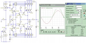
As a reference see picture above for approx operating point. Yes it will run positive grid occasionally but still quite linear, and have low z drive to grid anyways.
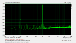
Have also removed cathode resistors and replaced with current sources, they were a short term fix to get the current up, but they were robbing me of gain, so the amp can now clip as intended.
Here is a plot of the today's distortion, for what its worth, running at about 2.5 watts
Hi Ontoaba,
re your interesting circuit, looks quite like Complementary Feedback Pair arrangement which has been my output stage of choice for last 20 years. I am using Darlingtons in this amp to avoid feedback, which is one of the aims of this project. I am quite interested in making linear output stage, and /or keeping output transistors turned on in standby, to reduce class b switching glitch during the alternate cycle. But as yet have not come up with the “circuit” good luck with you efforts.
Attachments
Thanks for these software h,
Hope you getting fine,
I am simulating this last night, will try it after my current project finished. It is now tripple EF(it should have thermal compensator with it), and simulated distortion is almost flat at 20Hz-20kHz
What happen with the feedback? umm, did you find something on your 20years output stage or is that really do something bad?
I do find worse thing with BJT differential input usage in loudspeaker driving.
This one has very weak feedback but may be effective to take classA BJT functionality for classAB operation.
Hope you getting fine
,I am simulating this last night, will try it after my current project finished. It is now tripple EF(it should have thermal compensator with it), and simulated distortion is almost flat at 20Hz-20kHz
What happen with the feedback? umm, did you find something on your 20years output stage or is that really do something bad?
I do find worse thing with BJT differential input usage in loudspeaker driving.
This one has very weak feedback but may be effective to take classA BJT functionality for classAB operation.
Attachments
Last edited:
Too late to edit, That was "three stage", not "triple EF"
Hi, h
It is now less than 10k pot position than before, there may be little different. But you cant compare its sound differences with only one.
Anyway, better stay to take good rest, and not too hard in work. I have another time playing with this kind input resistor, may be I'll play with it again when built this circuit.
- Status
- This old topic is closed. If you want to reopen this topic, contact a moderator using the "Report Post" button.
- Home
- Amplifiers
- Solid State
- Class A hybrid power dac project