The obvious answer to reducing the DC offset voltage is buy a different hFE range of transistors. If for example you have only BC550C, then obtain a few BC550B or ungraded BC550 to try pairing with them. As the BC series though-hole parts are becoming obsolete, you could just as easily substitute 2SC1815, 2SC1845 or other low noise TO92 transistors in at least two grades which are still available, though Chinese manufactured now.
I don't recommend matching the LTP collector resistors or squeezing trimpots onto the board so that you can force the balance of emitter currents either but the latter it is an option if you don't care much about keeping to the original Naim design topology. NAP series amplifiers are the model for NCC and Hacker variations so that's worth consideration.
FWIW, balancing the LTP as a true differential pair is a sure-fire way to ruin the sound quality of NAP designs but some builders only want a working amplifier - they've never heard a Naim anyway so I guess it doesn't matter to them what sound quality it has.
The power supply can be varied somewhat, according to your output requirements. The NAP 110 and 140 used +/-34V rails and the rest were nominally +/-40V. There were minor adjustments to the bias current setting resistors for the LTP and VAS sections in the smaller models accordingly.
The larger NAP250 and 135 mono models still had +/- 40V rails but regulated, to deliver more power with safety. Being more or less clones, NCC200 and Hacker NAP have similar limitations according to heatsinking capability, power transistor dissipation and the Vce max. rating of the VAS and small signal transistors. Be aware that bias stabilty depends on stable air currents circulating inside the aluminium case - don't use a separate heatsink, nor a ventilated or oversized case without considering the appropriate amount of heat transfer to the Vbe multiplier transistor. Bias current can take ages to stabilize before it can be set correctly and the box must also be closed for stable air currents to form and hopefully keep the current fairly consistent for the average power level it is working at. The heat spreader normally fitted to early NAP models was a necessary part of the thermal design too.
The hFE of genuine BC546 hFE is a bit low for a Naim clone. Max. hFE is only B grade where C grade is specified but the noise level is usually better than specified and comparable to low noise types. I have also used BC239C, BC549C, BC214C (Texas Instruments) BC414C (Unitra) and a few Japanese types with few problems in getting DC offset to <10 mV. The quantities I bought also had wide variations of hFE so that was easy.
Usually, you would want the input transistor pair to be matched for a proper, balanced response but not with early Naim amplifiers which have a different approach to sound quality in their modified electronic design. Some folk like it, others just don't like the idea of compromising technically correct electronic designs to get better sound quality.
Usually, you would want the input transistor pair to be matched for a proper, balanced response but not with early Naim amplifiers which have a different approach to sound quality in their modified electronic design. Some folk like it, others just don't like the idea of compromising technically correct electronic designs to get better sound quality.
The BC546B I have used had hFE=289. I had build the Avondale NCC200 and there was this reccomandation to use the different hFE by 10% between the 2 input transistors to assure the DC offset. I think I had just a little "bad luck" to have Some of the transistors you used have a lower VCE voltage, Can I use them safely?
The DC offset at the speaker outputs could be adjusted by changing the 620ohm resistor value at the emitter of TR3 in the diagram. You could try installing 560, 680 or 470 ohms and note the value of DC offset with each change. Then fine tune the final value using parallel resistor configuration. For example, if after experimenting, you need the value of 594 ohms to get the DC offset right (+- 15mV) then use both 680 and 4700 ohms parallel in place of TR3 emitter resistor.
Other way to get the DC offset right is by using HFE mismatch for the LTP transistors ala Naim. This is a long way approach. Need to test each transistor (TR1 and TR2) and match specs to within 10% of value. For example TR1 HFE511 and TR2 HFE494 (I'm using BC239C here). Then you don't need to change the 620 ohms resistor.
Other way to get the DC offset right is by using HFE mismatch for the LTP transistors ala Naim. This is a long way approach. Need to test each transistor (TR1 and TR2) and match specs to within 10% of value. For example TR1 HFE511 and TR2 HFE494 (I'm using BC239C here). Then you don't need to change the 620 ohms resistor.
Neither Avondale's NCC200 design or 99% of NAP140 clones are based on NAP140. The clones and kits are generally based on an old and widely published version of early model NAP250 - minus its discrete power supply regulation boards. That means the clone designs predate a lot of newer ideas and circuit design options that are now commonplace. After 40+ years development, though, we do find Naim circuits more in line with modern day, simulation driven trends - for better or worse.
Last edited:
I'm not sure about that; for very low frequencies( <100hz) there are some oscillation I think. Not always, for some frequency and some music form. I don't know exactly. Also, I don't know how to find out it in LTspice ") Oscillation's source may be PSU, output filter or what ever I don't know
Oscillation's source may be PSU, output filter or what ever I don't know
I absorbed that, it looks like speaker or room oscillation in low frequencies. Speaker was KEF R3 it's 180w and very good speaker. It can't be source of oscill. Room was 10m long, You can hear very low freq. I couldn't say it's not due to the room. but, I don't think Thank you...,
Oscillation's source may be PSU, output filter or what ever I don't know I absorbed that, it looks like speaker or room oscillation in low frequencies. Speaker was KEF R3 it's 180w and very good speaker. It can't be source of oscill. Room was 10m long, You can hear very low freq. I couldn't say it's not due to the room. but, I don't think
Thank you...,When you are clear on how the coil's LR impedance works to damp oscillation, it's easier to understand and perhaps calculate what L and R values will be suitable for a particular amplifier design. NAP designs have no coil at all - just the inductance + capacitance of 3-5m length of a certain (old) specification of twinflex cable. Note that the resistance is there mainly to damp the reactance (reduce the peak, i.e. circuit Q) and hence the likelihood of further instability.
https://www.diyaudio.com/community/...an-inductor-on-my-class-ab-amp-output.346796/
NCC200 obviously does have a coil in order to eliminate the dependence on a cable but choose one complete design or the other - not some random mix of parts of both designs which is sure to result in stability problems of one type or another.
Last edited:
Re: room resonance or reverberation.
If you have headphones, simply check first, that the effect persists or not without the speakers working. They don't need to be audiophile quality to check for this type of bass problem. You could also do other things, like hanging heavy curtains on any bare walls to damp reverberation but that may not be the problem and it's likely expensive and difficult to do, especially when others living in your home object to your experiments .
.
If you have headphones, simply check first, that the effect persists or not without the speakers working. They don't need to be audiophile quality to check for this type of bass problem. You could also do other things, like hanging heavy curtains on any bare walls to damp reverberation but that may not be the problem and it's likely expensive and difficult to do, especially when others living in your home object to your experiments
.I increased the inductor value; no change. I'm trying to change input low pass filter; degrasing 10uf capacitor value. I tried to change with 1uf film capacitor. Bass is ok but, sound changedFirst of all, kit's inductor is not 1uH. When I calculate, it's less than 0.5uH. I will try to change it (if diameter 12mm, length 15mm, number of turns 12 -> 1uH).
I will try with 1uf, 2.2uf, 4.7uf tantal. Also, 10uf another type tantals A 10uf film cap is ideal but I assume you used a polyester or MKT type. It would better to have a polypropylene type, perhaps MKP but that would mean very large - large enough to pick up hum and noise and feed it back through the amp. There are ways of shielding the caps but you need to be aware of the noise sensitivity problem and to check it out thoroughly. Perhaps that's why a tantalum type remained in use for so many years.
BTW, what do you want to do with the LP filter and why change it anyway?
BTW, what do you want to do with the LP filter and why change it anyway?
Last edited:
low frequency (<100hz) there was a oscillation, perhaps bass quitar vibrations was increased. I changed 10uf tantal with another one. Now, I'm listening, it looks like better. If not I will decrease the value of capacitor.A 10uf film cap is ideal but I assume you used a polyester or MKT type. It would better to have a polypropylene type, perhaps MKP but that would mean very large - large enough to pick up hum and noise and feed it back through the amp. There are ways of shielding the caps but you need to be aware of the noise sensitivity problem and to check it out thoroughly. Perhaps that's why a tantalum type remained in use for so many years.
BTW, what do you want to do with the LP filter and why change it anyway?
Speakers return connections to ground was with only one cable (2.5mm radius). I splited two. There is a big difference in sound.More likely a grounding issue than the dc blocking cap.
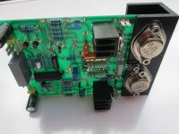
Hello, I would like to ask where the aluminum U-profiles shown in the picture can be purchased.
Basically, the sizes are 31.75mm/31.75mm/31.75mm/4.76mm.If it cannot be bought in these dimensions, then at least indicate a manufacturer with close to these dimensions. I mean the profile for the power transistors. Thanks in advance.
Basically, the sizes are 31.75mm/31.75mm/31.75mm/4.76mm.If it cannot be bought in these dimensions, then at least indicate a manufacturer with close to these dimensions. I mean the profile for the power transistors. Thanks in advance.
Attachments
- Home
- Amplifiers
- Solid State
- NAP140/NCC200 Clone with PSU