Impressions
I've been living with this amp for about six months at the heart of my active crossover Linkwitz Pluto-clone (a.k.a. Pluto-Nix) speakers.
The amp never fails to impress. Sonics are dynamic and crystal clear w/ 100W of beautiful Thermaltrak power. The speaker protection/voltage regulator is a work of genius; a John Linsley Hood (JLH) design. The amp was a joy to build.
Hopefully this amp will serve many years of enjoyment. If you're interested in a DIY Class AB you can't go wrong with this design. Single side board layouts, schematics, and BOM are available to craft by hand.
Excellent work, dado!
![DADO-TT-TMC-7-2-g-2.LAY].jpg](/community/data/attachments/282/282190-6940b5405a468bea5b4f359478a55adb.jpg)
updates
It looks like you made a number of changes to the design since my build. Could you please give a brief explanation of the changes and post updated schematics and non-inverted layout for the photo-resist etching method?
Most notably it looks like you changed the grounding scheme and removed the output inductor? It also looks like you added an option for a through-hole J3 next to the SMD
/Mason
Here is improved PCB single side Layout if someone is interested I will provide pdf files.
dado
It looks like you made a number of changes to the design since my build. Could you please give a brief explanation of the changes and post updated schematics and non-inverted layout for the photo-resist etching method?
Most notably it looks like you changed the grounding scheme and removed the output inductor? It also looks like you added an option for a through-hole J3 next to the SMD
/Mason
Hi Mason,It looks like you made a number of changes to the design since my build. Could you please give a brief explanation of the changes and post updated schematics and non-inverted layout for the photo-resist etching method?
Most notably it looks like you changed the grounding scheme and removed the output inductor? It also looks like you added an option for a through-hole J3 next to the SMD
/Mason
There is no changes in the schematic just the layout. The output inductor and coresponding resistor are moved directly to the loudspeaker terminals, as suggested in the other thread. I will attached the pdf files tomorow.
regards Damir
What about asking for copies of the relevant posts in the other Threads to be brought across to here?
Make a list and ask the Mods to implement the copying.
Thank you Andrew for suggestion. You meant the layout discution, did you?
dado
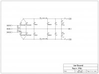
May I have Single side board layouts, schematics, and BOM's to craft by hand photo, for PSU and speaker protection/voltage regulator,please?
Thanks,

Here it is.
dado
Attachments
Here it is.
dado
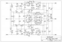
I found an error on the PS regulator PCB. There was missing connection between Q9 emitter and the ground. Here are correct pdf files.
dado
Attachments
![PSregulator-BJT-b.LAY]-error.jpg](/community/data/attachments/276/276503-6fbaf4f941ec8b83a0f83d9e82a85572.jpg)
This is new PS Regulator Layout, made to follows the role for less interference with the power lines (at list I hope, comments wellcome). The schematic is not changed.
Next step, better layout for the amp, hopping to get even better performance for this TT amp.
dado
Next step, better layout for the amp, hopping to get even better performance for this TT amp.
dado
Attachments
![PSregulator-BJT-c.LAY].jpg](/community/data/attachments/283/283773-f5a92799351aadfd8b0cd85412072499.jpg)
Shouldn't there be a diode from output to input of the regulator so output caps don't discharge through the pass transistors and hatever else? Also, R28 seems redundant, as the collectors of Q4 and Q2 ill have scores of kR impedance and only several pF of capacitance. Because of their high impedance R28 ill not matter much, like it ould if Q15 ere driven by a lo-impedance source.
Shouldn't there be a diode from output to input of the regulator so output caps don't discharge through the pass transistors and hatever else? Also, R28 seems redundant, as the collectors of Q4 and Q2 ill have scores of kR impedance and only several pF of capacitance. Because of their high impedance R28 ill not matter much, like it ould if Q15 ere driven by a lo-impedance source.
Thank your for the comments. A diode across power regulator transistor could not help to much as at the input of the regulator are big caps in the PSU, so smaller caps at the output or on to amp board will discharge faster thtough the amp and R22, R23, R122, R123.
R28 is redundant and I put it there just in case, it does not do any harm. This PS regulator(old layout) is in working amp and behaves as expected. It could be better for sure, but until now I never received any comment. Could you suggest more, also what about the new layout?
dado
Actually I really like that layout.
For the circuit, if you have an experimenting spirit and a good signal generator, you can do a lot. But only if you ant to. If you are satisfied ith the regulator I see no reason to improve it.
For one thing, I think regulators are somehat misapplied. A regulator too fast ill make you unable to use local decoupling or lo-ESR capacitors. This isn't necessary and quite possibly hurtful. After all, 1 inch of decoupling alays does better than 6 inches of trace beteen the regulator and the circuit. A regulator that bites off more than it can che ill oscillate ith films inches aay.
So it is important to kno hat causes oscillation into capacitive loads and ho to make a regulator that is benign. Your regulator looks like it's pretty slo, not high-performance, so it probably fits this profile.
Using a regulator does not mean you have to use small output capacitors. It shouldn't anyays, this can be fixed in design. But you need a good signal generator to be able to verify and adjust in real life.
I have a Tektronix FG504. I've had to fix it several times but it's all I could ask for. Do you have a good one?
- Status
- This old topic is closed. If you want to reopen this topic, contact a moderator using the "Report Post" button.
- Home
- Amplifiers
- Solid State
- ThermalTrak+TMC amp