Emitter degeneration on which transistors? The pre-drivers, the drivers, or the outputs? Or all of them?
Sorry AndrewT I did no answer before. It is pre-drivers degeneration.
dado
Dadod, the 2SA970/C2240 models have very low Cje. Models with low Cje probably won't perform like the actual devices, and may be much faster even if the Ft measurement in correct. My models show 5pF, but this was obviously added on by me or someone else, and in reality it may be much larger. I would stick with models from Cordell or other members of the forums. You may try Cordell's BC56x0C or A1381/C3503 models instead, which are known to be accurate.
Dadod, the 2SA970/C2240 models have very low Cje. Models with low Cje probably won't perform like the actual devices, and may be much faster even if the Ft measurement in correct. My models show 5pF, but this was obviously added on by me or someone else, and in reality it may be much larger. I would stick with models from Cordell or other members of the forums. You may try Cordell's BC56x0C or A1381/C3503 models instead, which are known to be accurate.
My models for 2SA970/2SC2240 show 5pF too and I don't think it is to low. Cob for those transistors is 3 to 4 pF.
I would appreciate if you do some simulations with your models and suggest improvements. I noticed that you have some fresh ideas and it could be interesting to here it from you.
I simulated with Crdell's models and I got three times more THD20k, but stability is the same and I think 5ppm is still good result.
dado
Cje is usually several times higher than Cjc. Cje is the main reason that Ft is low at low currents and rises steadily with Ic. If Cje is too low, Ft at low currents will be way too high. If I could see an Ft vs. Ic chart for the A970/C2240 I could put in a reasonable value, but this information is not in the datasheets. The reason I think 5pF is a guess is that in the model, it is actually gives as "5pF" as opposed to Cjc which is in exponential form with numbers after the decimal, say "6.221e-11". Someone probably added it later so the models wouldn't be totally wrong, and due to the lack of numbers after the decimal it was probably a bad guess.
Consider these models for instance, which I modified:
These are the 2SC3423/A1360, a PCT process Toshiba transistor like the 2SA970. They are generally held in high regard. The original models had 2pF for Cje! Thus, even at 1mA the models showed an Ft of 200MHz. To find the right Cje value I first took the correct value of Cjc from the datasheet, then I use Tf to adjust for proper Ft at 10mA (high current Ft). Then I adjusted Cje to put 500uA Ft at the right value (low current Ft, dominated by the lowered transconductance caused by Cje). I also changed some other parameters, not sure which.
Granted, these are 1W transistors and the 2SA970 is 300mW. But they are still pretty similar.
The BC550C/560C are still nearly unbeatable, except for Vceo. However this works to their advantage because they have very good low-Vce characteristics. They are also pretty common. Unfortunately using them in a high voltage amp like this could be difficult. I'm pretty sure they would do great justice in the current mirror, there is nothing better I've found for that Vce level (aside from the BC3x7, but these have worse general specs). If you bootstrap the VAS collector to the positive filtered supply, you can use the BC560C there and you eliminate a source of PSRR, as well as close the drive current loop through the VAS base, which could aid in stability.
Consider these models for instance, which I modified:
Code:
.MODEL 2SC3423_k NPN (IS=10.000E-15 BF=156.29 VAF=100 IKF=72.247E-3 XTB=1.5 ISE=103.97E-15 NE=1.5392 BR=2.3164 VAR=100 IKR=10.000E-3 ISC=10.000E-15 NK=.4999 CJE=28p CJC=4.2p VJC=.35 MJC=.21196 TF=550p VTF=8.7934 ITF=114.51 TR=25.505E-6)
.MODEL 2SA1360_k PNP (IS=116.73E-15 BF=120 VAF=100 IKF=78.684E-3 ISE=297.72E-15 NE=1.5511 BR=.77363 VAR=100 IKR=1.0217 ISC=26.920E-15 NC=2.9970 NK=.49889 RC=4.5038 CJE=31p MJE=.33333 CJC=6.3p VJC=.35 MJC=.26272 TF=255p XTF=84.382 VTF=7.0050 ITF=.11443 TR=10.000E-9)Granted, these are 1W transistors and the 2SA970 is 300mW. But they are still pretty similar.
The BC550C/560C are still nearly unbeatable, except for Vceo. However this works to their advantage because they have very good low-Vce characteristics. They are also pretty common. Unfortunately using them in a high voltage amp like this could be difficult. I'm pretty sure they would do great justice in the current mirror, there is nothing better I've found for that Vce level (aside from the BC3x7, but these have worse general specs). If you bootstrap the VAS collector to the positive filtered supply, you can use the BC560C there and you eliminate a source of PSRR, as well as close the drive current loop through the VAS base, which could aid in stability.
MPSA18
I did a simulation with MPSA18, look here: http://www.diyaudio.com/forums/soli...one-seen-front-end-before-22.html#post3018706
dado
Dado a simulation and real life are a little different, but if the model for mpsa represents the real part the better. In the case where you have it in the LTP yes it will outperform the bc s and most other small signal transistors. Its very high beta helps offsets, PSRR and common mode rejection, in most examples I have found they also have lower capacitances than practically all small signal transistors bar RF transistors. Their noise could be a little higher but its not a big issue with power amps. A high VCEO would have been nice but there are ways around that as in your amp.
Dado, there are no good models for the 2SC2240/A970. I've tried all I could find. I would suggest you simulate with something else, or your results won't be right.
Thanks keantoken,
Do you know good models for 2SC1845/2SA992?
Could you show how to do this as I am not sure I understud it?bootstrap the VAS collector to the positive filtered supply, you can use the BC560C there and you eliminate a source of PSRR, as well as close the drive current loop through the VAS base, which could aid in stability.
dado
Dado, there are no good models for the 2SC2240/A970. I've tried all I could find.
What is the problem with the model(s)?
Have you tried Bob Cordell's book instructions to create a satisfactory model of your own?
This is a transistor I plan to use so I would be happy to help create a usable model.
Best wishes
David
BTW. What is the Toshiba PCT process claimed for these transistors?
Last edited:
Firstly the models don't specify Hfe grade, which is somewhat important. Secondly, Cje is usually just a guessed value, way too low, causing it to be too fast at low currents. In the one model where Cje looked realistic, Tf was not defined, causing high-current Ft to be way too high. The KSC2690/A1220 models had the same problem despite excellent Hfe modeling, so I added Tf myself. So perhaps that one model could be made accurate, but there is no satisfactory basic model for the complement, and I haven't had the desire to make reasonable models for them.
http://www.diyaudio.com/forums/solid-state/19233-spice-models-2sa970-2sc2240.html
I've messed around a lot with BJT models. I have several models I've tweaked or created by hand. This was one such:
http://www.diyaudio.com/forums/solid-state/209689-new-2sc5200-2sa1943-spice-models.html
I also made models for the 2SC4883A/A1859A and 2N5769/5771. Here are the models I'm using for the 1845/992:
They are good enough for me so far, though I don't use them much. I had to lower RC in the 1845 because the original model had the value way too high, causing bad behavior in current mirrors and CCS.
I don't know what the PCT process is. I don't know anything about processes or fabrication.
My questions is, if everyone now is able to just make their own models whenever they like, why hasn't anyone posted their custom models but me? Am I the only one who wants to share?
Granted, I tweak my models by hand. I never learned how to use spreadsheets. I know what each parameter does, I've done this a lot. It may not have the nth degree of accuracy, but I think most of my models have quorum, and transistors are not all the same anyways.
http://www.diyaudio.com/forums/solid-state/19233-spice-models-2sa970-2sc2240.html
I've messed around a lot with BJT models. I have several models I've tweaked or created by hand. This was one such:
http://www.diyaudio.com/forums/solid-state/209689-new-2sc5200-2sa1943-spice-models.html
I also made models for the 2SC4883A/A1859A and 2N5769/5771. Here are the models I'm using for the 1845/992:
Code:
.MODEL KSC1845_k npn IS=1.075431E-13 BF=600.7 NF=1 BR=13.565 NR=1 ISE=1.98107E-13 NE=2 ISC=1.8378E-11 NC=1.5 VAF=82.803 VAR=20.6691 IKF=0.596 IKR=0.0190546 RB=157 RBM=12.092 IRB=1.258925E-6 RE=1.5 RC=0 CJE=2.057447E-11 VJE=0.7300286 MJE=0.3619943 FC=0.5 CJC=4.525739E-12 VJC=0.5 MJC=0.3659045 XTB=1.7281 EG=1.1809 XTI=3 TF=3.14E-11 Vceo=120 Icrating=50m mfg=Fairchild
.MODEL KSA992 pnp ( IS=5.7544E-14 BF=348.1 NF=1 BR=3.62 NR=0.95 ISE=5.7544E-15 NE=1.5 ISC=1.8378E-14 NC=1 VAF=144 VAR=16.68 IKF=0.298 IKR=0.0525 RB=140 RBM=16.084 IRB=1.4125E-3 RE=0.38 RC=0.47 CJE=2.3093E-11 VJE=0.855 MJE=0.4104 FC=0.5 CJC=8.9251E-12 VJC=0.5 MJC=0.3497 CJS=0 VJS=0.8 MJS=0.33 XTB=1.2849 EG=1.1603 XTI=3 XCJC=0.3062 Vceo=120 Icrating=50m mfg=Fairchild)
They are good enough for me so far, though I don't use them much. I had to lower RC in the 1845 because the original model had the value way too high, causing bad behavior in current mirrors and CCS.
I don't know what the PCT process is. I don't know anything about processes or fabrication.
My questions is, if everyone now is able to just make their own models whenever they like, why hasn't anyone posted their custom models but me? Am I the only one who wants to share?
Granted, I tweak my models by hand. I never learned how to use spreadsheets. I know what each parameter does, I've done this a lot. It may not have the nth degree of accuracy, but I think most of my models have quorum, and transistors are not all the same anyways.
I forgot to mention, I may have already created suitable models for the C2240/A970 if the datasheets included an Ft vs. Ic graph. This is necessary to find the right value of Cje in the case it is not included in the datasheet.
If a a few or more people were willing to work on a library of good transistor models to share with everyone, I would be happy to pitch in. Actually just today I have a good start on that. I have considered taking model commissions in return for money or parts through the mail; right now I'm trying to find the best seller of non-counterfeit 2SC3284/A1303 because I want to build a nice amp not unlike Dado's (although quite different).
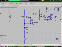
Here is an example of the buffer bootstrap thingy. R37 needs to be chosen so Q15 has a comfortable Vce. Notice the drive current through Cbe returns to the buffer collector in a very short loop. Otherwise it goes all the way around the entire perimeter of the amp through several decoupling caps, and who knows what happens in between. Maybe it is negligible, maybe not.
If a a few or more people were willing to work on a library of good transistor models to share with everyone, I would be happy to pitch in. Actually just today I have a good start on that. I have considered taking model commissions in return for money or parts through the mail; right now I'm trying to find the best seller of non-counterfeit 2SC3284/A1303 because I want to build a nice amp not unlike Dado's (although quite different).
Here is an example of the buffer bootstrap thingy. R37 needs to be chosen so Q15 has a comfortable Vce. Notice the drive current through Cbe returns to the buffer collector in a very short loop. Otherwise it goes all the way around the entire perimeter of the amp through several decoupling caps, and who knows what happens in between. Maybe it is negligible, maybe not.
Attachments
Last edited:
I forgot to mention, I may have already created suitable models for the C2240/A970 if the datasheets included an Ft vs. Ic graph. This is necessary to find the right value of Cje in the case it is not included in the datasheet.
If a a few or more people were willing to work on a library of good transistor models to share with everyone, I would be happy to pitch in. Actually just today I have a good start on that. I have considered taking model commissions in return for money or parts through the mail; right now I'm trying to find the best seller of non-counterfeit 2SC3284/A1303 because I want to build a nice amp not unlike Dado's (although quite different).
Here is an example of the buffer bootstrap thingy. R37 needs to be chosen so Q15 has a comfortable Vce. Notice the drive current through Cbe returns to the buffer collector in a very short loop. Otherwise it goes all the way around the entire perimeter of the amp through several decoupling caps, and who knows what happens in between. Maybe it is negligible, maybe not.
Thanks keantoken, I will simulate it to see what I could get.
Could you show your amp schematic, I am very interested to see it, even if I do not intend to build new amp in near future.
dado
OK. Easily done. Just two models with different BFFirstly the models don't specify Hfe grade, which is somewhat important.
OK. Put plausible value of CJE and TF from datasheet FtSecondly, Cje is usually just a guessed value, way too low, causing it to be too fast at low currents. In the one model where Cje looked realistic, Tf was not defined, causing high-current Ft to be way too high.
Yes, some of them don't inspire confidence
") .
. Well, Andy and Bob share their models. And other people try to share the factory models they have found - even those that don't inspire confidence.I've messed around a lot with BJT models. I have several models I've tweaked or created by hand...
My questions is, if everyone now is able to just make their own models whenever they like, why hasn't anyone posted their custom models but me? Am I the only one who wants to share?
Granted, I tweak my models by hand. I never learned how to use spreadsheets. I know what each parameter does, I've done this a lot. It may not have the nth degree of accuracy, but I think most of my models have quorum, and transistors are not all the same anyways.
Andy's site has an impressive amount of work on the use of spreadsheets to try to best fit the data. Not sure how much better than a hand fit in practise.
I don't have the equipment to measure Ft as a function of collector current so it will have to be estimated.I forgot to mention, I may have already created suitable models for the C2240/A970 if the datasheets included an Ft vs. Ic graph. This is necessary to find the right value of Cje in the case it is not included in the datasheet.
I want to build a nice amp not unlike Dado's (although quite different).
I want to build a nice amp like Dado's but quite different too
I want to build a nice amp like Dado's but quite different too
Dave, please show your schematic too.
dado
I have not changed your schematic any. As your amp inspired me to mess with EF3 topology, instead I went ahead and added a beta enhancer and EF3 onto my current so-far-so-secret power amp design. It is this I plan to build using the remains of a broken HK AVR45 amp and the 2SC3284 outputs. I would really appreciate it if someone knows of a good source of 2SC3284Y. I've found several options for lower Hfe grades, few of which are genuine for sure. After I've explored my design in more detail I think I will share it on the forum, but that is some time from now.
Dave,
I haven't messed with the 2SC2240/A970 models because I haven't felt the need to use them. A friend has just mailed me a package of the BL grade though, so maybe I should. One thing I don't know much about is noise. I would not know how to model noise correctly, and that is most of the spec of this pair. I can get Vbe, Hfe and Ft curves set up, and with good references I might be able to quickly learn how to do noise, but you may have to do that part.
Cje could be directly measured, if you have something that can measure around 25pF with a test signal as small as 100mV. Then there will be no guessing Ft. I don't have any kind of measuring bridge though I seem to need one. Maybe now that I think about it I really could measure this...
I think the closest approximation will be to establish Cje and Cjc and then adjust Tf to get the Ft to match the datasheet. I could be missing something if one of the h parameters has to do with Ft, that's another thing I haven't studied.
Dave, please show your schematic too.
dado
Thank you but I have only started to define. No schematic yet. But I want to build at about the level of complexity that you and Andrew (Bonsai) have achieved. Not as complicated as Edmond and Ovidu's masterpiece but better performance than the typical Blameless clone.
So far it looks like.
Complementary symmetry front end - low noise is important for compression drivers.
A two transistor "VAS" -
A triple BJT ThermalTrak OPS - probably as CFP + EF.
TMC/TPC and Input Inclusive compensation.
I would like to use current mirrors but the problems with that + Symmetrical IPS are well known.
So I currently research the options
1. Bob Cordell's resistor load - Reasonably simple
2. Common Mode Control Loop (CMCL) - can this be done reasonably simply?
3. Edmond Stuart's SuperTIS - Very clever but untested, so potential development problems.
There is a lot of old discussions on DIYAudio to read about this and I don't want to write until I understand it - so I don't waste anyone's time. But when I have a circuit I will certainly show it for criticism and review.
You have put almost all what was discussed here in this forum. Do not over engineered it, keep it "as simple as possible, but not simpler".
I am impresed with Stuart's amps and I learned a lot from him, but one thing keep me from implementation, to complicated PCB layout and I don't think I am qualified to develop good enough one. Still with simpler design you can get very close to his level of distortion, simulated only, but Stuart's amps were simulated only too.
Complementary symmetry front end is not important for me, I am more to D. Self reasoning.
What is Bob Cordell's resistor load, I bought his book but don't remember that?
dado
Yes, Bob does not discuss noise models much and the local library had their SPICE/Semiconductor texts on loan when I last checked. As I understand it Rbb is a primary factor for white noise so RB is important. Theoretically this won't conflict with the requirement to use RB to adjust Vbe at different currents.One thing I don't know much about is noise. I would not know how to model noise correctly, and that is most of the spec of this pair. I can get Vbe, Hfe and Ft curves set up, and with good references I might be able to quickly learn how to do noise, but you may have to do that part.
I will check how 1/f noise is modelled in SPICE, if at all. I don't recall I have seen it discussed.
If you measure Cje then Ft is still an independent variable. That's why there's CJE and TF of course.Cje could be directly measured, if you have something that can measure around 25pF with a test signal as small as 100mV. Then there will be no guessing Ft.
That sounds the way to me too.I think the closest approximation will be to establish Cje and Cjc and then adjust Tf to get the Ft to match the datasheet. I could be missing something if one of the h parameters has to do with Ft, that's another thing I haven't studied.
Best wishes
David
- Status
- This old topic is closed. If you want to reopen this topic, contact a moderator using the "Report Post" button.
- Home
- Amplifiers
- Solid State
- ThermalTrak+TMC amp