TT-Triple
Another update:
1) I managed to solve why the PS Regulator speaker protection was randomly turning on, although the problem is not caused by the amplifier itself. Now that summer is approaching I have the air conditioning enabled. Occasionally when the HVAC condenser fan turns on outside, it introduces some combination of voltage and EMI transients into my electrical network. I verified this behavior by turning on and off breakers on the HVAC circuit in my home. Every time the speaker protection would immediately enable after I switched the circuit breaker from off to on (amp located on a separate circuit).
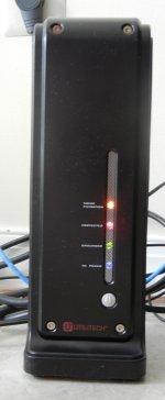
I installed a surge protection power strip with built in EMI/RFI filtering into my system as a solution (see attached photo). So far so good; this seems to have solved the problem. No cutouts, and the central air conditioning has been on for the last few days.
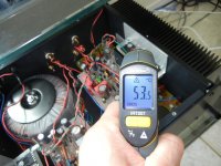
2) I measured the amplifier heatsink cutout temperature, and I've never seen it rise above 55C, even after listening for several hours at extended volume (see attached photo).
3) As mentioned in a previous post, ground loop noise is effectively eliminated.
4) The speaker protection employed in the PS Regulator is very unique. It does not employ relay contacts in the signal path, which introduce noise into the signal. Dado managed to modify an old John Linsley Hood (JLH) design from the 1980's. As explained above, it works all too well. I'm confidant that my expensive speakers will be protected by this circuit.
5) I can't stress enough how phenomenal this amplifier sounds.
/Mason
Another update:
1) I managed to solve why the PS Regulator speaker protection was randomly turning on, although the problem is not caused by the amplifier itself. Now that summer is approaching I have the air conditioning enabled. Occasionally when the HVAC condenser fan turns on outside, it introduces some combination of voltage and EMI transients into my electrical network. I verified this behavior by turning on and off breakers on the HVAC circuit in my home. Every time the speaker protection would immediately enable after I switched the circuit breaker from off to on (amp located on a separate circuit).
I installed a surge protection power strip with built in EMI/RFI filtering into my system as a solution (see attached photo). So far so good; this seems to have solved the problem. No cutouts, and the central air conditioning has been on for the last few days.
2) I measured the amplifier heatsink cutout temperature, and I've never seen it rise above 55C, even after listening for several hours at extended volume (see attached photo).
3) As mentioned in a previous post, ground loop noise is effectively eliminated.
4) The speaker protection employed in the PS Regulator is very unique. It does not employ relay contacts in the signal path, which introduce noise into the signal. Dado managed to modify an old John Linsley Hood (JLH) design from the 1980's. As explained above, it works all too well. I'm confidant that my expensive speakers will be protected by this circuit.
5) I can't stress enough how phenomenal this amplifier sounds.
/Mason
Attachments
Dadod, have you measured the bias stability in real life? Does it overcorrect or undercorrect? Also, the rectified current through the negative driver base will cause bias to drift down with power, and this is independent of temperature effects. This is one reason to use a CFP Vbe multiplier.
Dadod, have you measured the bias stability in real life? Does it overcorrect or undercorrect? Also, the rectified current through the negative driver base will cause bias to drift down with power, and this is independent of temperature effects. This is one reason to use a CFP Vbe multiplier.
If you read trough the thread you can notice that I changed resistor in one cannal to have the bias stable. In real life I try to hove a bit overcompensated, just a bit. It looks that one transistor Vbe multiplier is sensitive to Hfe. I followed yours posts, very interesing, But to use a CFB Vbe multiplier was to late for me as I hade the PCBs made for all six channels I am going to make. I am quite satisfied with the thermal stability and after prolong listening it was not changed more then 10%.
dado
It's a nice amp Dadod. It seems a bit daft to say this after it's all been built, but:
At high powers, 3rd harmonics can be reduced by adding two resistors, from emitters of outputs to bases of drivers. These resistors compensate for high-current Hfe droop because the logarithmic Vbe imposed across them causes them to draw less current at high output currents. Depending on the input stage and VAS linearity this may increase 2nd harmonic distortion below these levels. If the input stage and VAS are not very linear the 2nd harmonics at low power levels will rise however. I wonder if this modification improves dynamics. I am not really sure if it works this way in a triple EF however, because it seems in this case most of the distortion comes from the output switching distortion voltage imposed across the VAS and Miller compensation.
Usually this modification eliminates the need for a CCS because the same function can be provided by a special bootstrap, and it makes the CCS useless anyway. The effect is to decrease output stage current gain, in return for linearity. That is to say, open-loop linearity increases unless the input and VAS stages are not very linear.
What would you suggest for a computer as a source? It generates so much of it's own noise.
At high powers, 3rd harmonics can be reduced by adding two resistors, from emitters of outputs to bases of drivers. These resistors compensate for high-current Hfe droop because the logarithmic Vbe imposed across them causes them to draw less current at high output currents. Depending on the input stage and VAS linearity this may increase 2nd harmonic distortion below these levels. If the input stage and VAS are not very linear the 2nd harmonics at low power levels will rise however. I wonder if this modification improves dynamics. I am not really sure if it works this way in a triple EF however, because it seems in this case most of the distortion comes from the output switching distortion voltage imposed across the VAS and Miller compensation.
Usually this modification eliminates the need for a CCS because the same function can be provided by a special bootstrap, and it makes the CCS useless anyway. The effect is to decrease output stage current gain, in return for linearity. That is to say, open-loop linearity increases unless the input and VAS stages are not very linear.
Add EMI/RFI filtering to the aircon. Source attenuation is always better than at receiver
What would you suggest for a computer as a source? It generates so much of it's own noise.
Thermal stability improvements?
Hi Dado
Very nice amp") It seems excellent performance at reasonable complexity. You have made a smart balance of improvements by TMC and ThermalTrak without too many problems from unproven techniques.
It seems excellent performance at reasonable complexity. You have made a smart balance of improvements by TMC and ThermalTrak without too many problems from unproven techniques.
I have one question. It seems a triple with CFP + EF would be as low distortion and a little easier to thermally stabilize. Did you consider this and reject it? Or just decide to stay with conventional, proven output circuit?
The CFP+EF circuit looks attractive and I am a little surprised it is not more common so that is why I ask. I explain my idea a bit more in Bonsai's E-amp thread if you are interested but I would like to have your opinion too.
Best wishes
David
Hi Dado
Very nice amp
It seems excellent performance at reasonable complexity. You have made a smart balance of improvements by TMC and ThermalTrak without too many problems from unproven techniques.I have one question. It seems a triple with CFP + EF would be as low distortion and a little easier to thermally stabilize. Did you consider this and reject it? Or just decide to stay with conventional, proven output circuit?
The CFP+EF circuit looks attractive and I am a little surprised it is not more common so that is why I ask. I explain my idea a bit more in Bonsai's E-amp thread if you are interested but I would like to have your opinion too.
Best wishes
David
Hi Dado
Very nice amp
I have one question. It seems a triple with CFP + EF would be as low distortion and a little easier to thermally stabilize. Did you consider this and reject it? Or just decide to stay with conventional, proven output circuit?
The CFP+EF circuit looks attractive and I am a little surprised it is not more common so that is why I ask. I explain my idea a bit more in Bonsai's E-amp thread if you are interested but I would like to have your opinion too.
Best wishes
David
Hi David,
I decided to stay with proven output circuit, I would not say conventional.
Today I simulated CFP + EF as in Roender amp and I couldn't get it stable without adding some capacitors, first between the drivers base-collector and it was just possible to simulate with 220pF, but with worst PM and GM then the triple EF.
I then put 100pF between predrivers base-collector and stability was better but distortion was close to ordinary triple. I am not sure how Roender get stable his OPS with no capacitors.
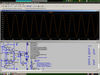
difference between ordinari Triple and CFP-EF:
EF Triple:
Fourier components of V(vout)
DC component:0.00212666
Harmonic Frequency Fourier Normalized Phase Normalized
Number [Hz] Component Component [degree] Phase [deg]
1 2.000e+04 3.084e+01 1.000e+00 -2.66° 0.00°
2 4.000e+04 2.768e-05 8.977e-07 94.19° 96.85°
3 6.000e+04 3.022e-05 9.801e-07 150.01° 152.68°
4 8.000e+04 1.558e-05 5.053e-07 -136.70° -134.03°
5 1.000e+05 4.853e-05 1.574e-06 -12.31° -9.65°
6 1.200e+05 8.743e-06 2.835e-07 -160.98° -158.32°
7 1.400e+05 1.272e-05 4.126e-07 29.92° 32.58°
8 1.600e+05 1.473e-05 4.778e-07 -139.96° -137.29°
9 1.800e+05 7.758e-06 2.516e-07 31.20° 33.86°
Total Harmonic Distortion: 0.000225%
CFP-EF:
Fourier components of V(vout)
DC component:0.00222449
Harmonic Frequency Fourier Normalized Phase Normalized
Number [Hz] Component Component [degree] Phase [deg]
1 2.000e+04 3.084e+01 1.000e+00 -2.66° 0.00°
2 4.000e+04 3.370e-05 1.093e-06 85.92° 88.58°
3 6.000e+04 2.753e-05 8.929e-07 150.93° 153.59°
4 8.000e+04 1.492e-05 4.837e-07 -135.18° -132.51°
5 1.000e+05 3.163e-05 1.026e-06 -14.48° -11.81°
6 1.200e+05 4.765e-06 1.545e-07 170.83° 173.49°
7 1.400e+05 7.618e-06 2.470e-07 119.75° 122.41°
8 1.600e+05 9.969e-06 3.233e-07 -142.38° -139.71°
9 1.800e+05 9.777e-06 3.171e-07 154.56° 157.22°
Total Harmonic Distortion: 0.000189%
Do you have proposal how to tame CFP-EF as it has potential?
dado
It's a nice amp Dadod. It seems a bit daft to say this after it's all been built, but:
At high powers, 3rd harmonics can be reduced by adding two resistors, from emitters of outputs to bases of drivers. These resistors compensate for high-current Hfe droop because the logarithmic Vbe imposed across them causes them to draw less current at high output currents. Depending on the input stage and VAS linearity this may increase 2nd harmonic distortion below these levels. If the input stage and VAS are not very linear the 2nd harmonics at low power levels will rise however. I wonder if this modification improves dynamics. I am not really sure if it works this way in a triple EF however, because it seems in this case most of the distortion comes from the output switching distortion voltage imposed across the VAS and Miller compensation.
Usually this modification eliminates the need for a CCS because the same function can be provided by a special bootstrap, and it makes the CCS useless anyway. The effect is to decrease output stage current gain, in return for linearity. That is to say, open-loop linearity increases unless the input and VAS stages are not very linear.
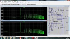
I am not sure what resistor value to use, and I simulated with 220ohm.
I don't see any 3rd harmonic reduction, look at FFTs. This simulation is at max power.
Could you suggest the resistors value?
dado
Attachments
I decided to stay with proven output circuit, I would not say conventional.
Today I simulated CFP + EF as in Roender amp and I couldn't get it stable without adding some capacitors..
I am not sure how Roender get stable his OPS with no capacitors.
...
Do you have proposal how to tame CFP-EF as it has potential?
dado
No proposal yet! I have a few ideas but need to think more.
I believe a few people did have some trouble with Roender's amp when they built copies. I will check their solutions.
I am interested in better thermal stability but lower distortion is a nice bonus. Even if, as Andrew notes, it's only 1.5 dB.
But your decision to stay with a proven output circuit while you tested TMC and ThermalTrak is very reasonable and seems to have worked well.
Best wishes
David
Is Dado an informal form of Damir?
Yes
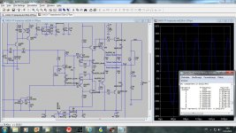
CFP compensation:
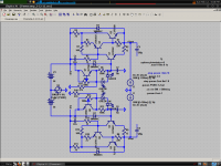
The best way is an RC across the B-E junction of the slave transistor. This has better performance then the Miller type (which doesn't necessarily work anyway) and it doesn't reduce PSRR. See attached schematic of my high-current K-multiplier.
Resistors:
I found in a double EF that 6.8k was the best value, reducing 3rd harmonic from -102db to -108db. This is at 18V into 6R with a single pair of outputs (try 15k resistors from output emitters to Q19 and Q21 emitters just to get close). I imagine it would be 15k or something like that for two pairs of outputs. Just lower or increase the value until you find the right value. If you don't like guessing you may inspect the phase of the third harmonic to determine whether you want to go up or down (overcomp vs. undercomp).
I don't know if it works the same for your heavily-buffered output stage. This technique has worked best for output stages where current gain nonlinearity was the largest concern for distortion. See attached schematic.
Furthermore, the Vbe transfer curve probably is not an exact fit to the high-current beta rolloff. So I think adjusting this compensation at max power level may eliminate the potential benefit from lower power levels where the fit is more accurate.
PS. Is this not a form of error correction?
Attachments
CFP compensation:
The best way is an RC across the B-E junction of the slave transistor. This has better performance then the Miller type (which doesn't necessarily work anyway) and it doesn't reduce PSRR. See attached schematic of my high-current K-multiplier.
Here is what I get now with RC across the B-E of the predrivers. Now the stability is similar to the Triple EF.
dado
Attachments
That looks good to me. I wonder if it will stay stable at high currents where the transconductance of Q19 and Q21 increases dramatically. This is one of the reasons I use degeneration in my Kmultipliers.
With degeneration of 2.2ohm distortion increases a bit.
CFP compensation:
Resistors:
I found in a double EF that 6.8k was the best value, reducing 3rd harmonic from -102db to -108db. This is at 18V into 6R with a single pair of outputs (try 15k resistors from output emitters to Q19 and Q21 emitters just to get close). I imagine it would be 15k or something like that for two pairs of outputs. Just lower or increase the value until you find the right value. If you don't like guessing you may inspect the phase of the third harmonic to determine whether you want to go up or down (overcomp vs. undercomp).
I don't know if it works the same for your heavily-buffered output stage. This technique has worked best for output stages where current gain nonlinearity was the largest concern for distortion. See attached schematic.
Furthermore, the Vbe transfer curve probably is not an exact fit to the high-current beta rolloff. So I think adjusting this compensation at max power level may eliminate the potential benefit from lower power levels where the fit is more accurate.
PS. Is this not a form of error correction?
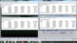
I simulated with resistors from 15k down to 6.8k and here are the results.
My opinion is that this does not help enough to reduce odd harmoniks to be implemented in the triple ops.
First up left is with no resistors and then is written a resistors values.
dado
Attachments
I guess it is not an issue due to the astronomical current gain of your output stage. It looks to me like voltage distortion appearing at the VAS output is much larger, along with distortion from compensation loading of the input stage. Have you tried TPC?
I was trying to find a schematic that I can simulate, but there are a lot of different schematics - which one should I use? Which one are you using?
I was trying to find a schematic that I can simulate, but there are a lot of different schematics - which one should I use? Which one are you using?
Also, try using the BC560C for the current mirror. Here you need a transistor with very good Vcesat parameters, the BC5xx and BC3x7 are better here than any transistor I've tried. The 2N5551 that are often used are just horrible. The KSA992 are also pretty bad. Look for the Hfe vs Vce curves.
I guess it is not an issue due to the astronomical current gain of your output stage. It looks to me like voltage distortion appearing at the VAS output is much larger, along with distortion from compensation loading of the input stage. Have you tried TPC?
I was trying to find a schematic that I can simulate, but there are a lot of different schematics - which one should I use? Which one are you using?
Here is the zip file.
Attachments
- Status
- This old topic is closed. If you want to reopen this topic, contact a moderator using the "Report Post" button.
- Home
- Amplifiers
- Solid State
- ThermalTrak+TMC amp