I'm planning to order some PCBs for this amp. I have to order a few. Are any of you interested in a set?
Thanks, Terry
Hi Terry,
As I changed connection of P1 trimmer pot I forgot to make metallization though the holes for P1 connection. It is minor error, but I hope you did not order the PCBs yet, here are rectified gerbers.
BR Damir
Attachments
Hi Guys,
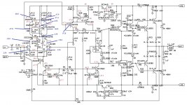
I am not giving up without a fight. I am posting again in hopes of maybe getting some fresh eyes on this. I replace Q3, Q4, Q5 and Q6 with matched pairs. The transistors I pulled read good and still matched but I went ahead and installed the new matched pairs just to be sure. I have the exact same issue. The collectors of Q4&5 are still 47.8V and the collectors for Q3&6 are still 46.8V. J1 & J2 have identical readings. The emitters of Q3&4 are both 3.84V. With yellow LEDs I now have 4.3V at the bases of Q3&4. So can someone please explain why I have a full volt more on the collectors of Q4&5 than I do at Q3&6? I am reattaching the latest schematic with the most recent measurement to make it easier for someone to examine.
Thanks, Terry
Attachments
Last edited:
Terry, perhaps a careful inspection to the PCB and the passive parts is needed. From your voltage reading across R6, there is a 10~11 mA current going through it, which is consistence to the design, given that the installed R6 is indeed 56-ohm. Check R6 and see it measures 56 ohms.
This 10~11 mA is supposed to have come from the positive rail +48V, splitting equally two ways through R12 and R14, all the way down and join by R10, R11, and P2. However, the voltage reading across R12 indicates no current, voltage across R14 indicates only 2 mA current. Eightr R6 on the board is a wrong value resistor or something else has bypassed the supposed current routes and took over supplying the current running through R6, if the latter case, you'll need to check the PCB and find out the bypass route.
This 10~11 mA is supposed to have come from the positive rail +48V, splitting equally two ways through R12 and R14, all the way down and join by R10, R11, and P2. However, the voltage reading across R12 indicates no current, voltage across R14 indicates only 2 mA current. Eightr R6 on the board is a wrong value resistor or something else has bypassed the supposed current routes and took over supplying the current running through R6, if the latter case, you'll need to check the PCB and find out the bypass route.
![DADO-TT-TMC-7-2-g-2.LAY] VBE correction.jpg](/community/data/attachments/426/426630-5d6e1a87418174bb8c28dd48e3f53062.jpg)
I got a chance to take some measurements. Hopefully this will help.
Thanks, Terry
I checked and rechecked the layout and could not find any fault. Terry, I see from your measurement some strange R3 current. Did you connect input gnd to the common star ground?
Yes I have jumpers between all three ground planes.
I didn't measure R3. Those are the values for R10. Sorry if I didn't mark that correctly.
Oh, I see, sorry.
Difference in CM currents (R12, R14) is a bit to big and Q5 Vce to low. Something's pulling that voltage down(or more correctly up to -V), and there are connected Q15 base and C5(I hope) only.
Hi Damir,
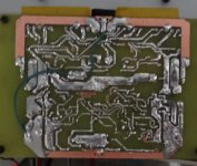
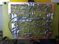
I see the differences. I just can't find the cause. Q15 base is connected to Q4c and Q5c and C5 only. I have checked for solder bridges throughout and believe I have a clean board. I am attaching a clearer picture of the foil side. I have the exact same issues with both boards.
Blessings, Terry
I see the differences. I just can't find the cause. Q15 base is connected to Q4c and Q5c and C5 only. I have checked for solder bridges throughout and believe I have a clean board. I am attaching a clearer picture of the foil side. I have the exact same issues with both boards.
Blessings, Terry
Attachments
Hi Damir,
I see the differences. I just can't find the cause. Q15 base is connected to Q4c and Q5c and C5 only. I have checked for solder bridges throughout and believe I have a clean board. I am attaching a clearer picture of the foil side. I have the exact same issues with both boards.
Blessings, Terry
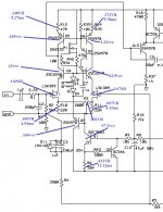
Terry I don't see those ground wires I market with red arrows. This should be connected as in the picture with thick wire on the back side and exactly as it is shown
BR Damir
By the way, Terry you did not connect input gnd, market as upside down T on the PCB, it is floating now connected with 10R to the GND. It is not important for voltage measurement, but for real listening you have to use separate ground wires from both gnd points.
Attachments
![DADO-TT-TMC-7-2-g-2.LAY].jpg](/community/data/attachments/426/426798-12e9941c88f2fd54441a6b4b67accec2.jpg)
Last edited:
Terry I don't see those ground wires I market with red arrows. This should be connected as in the picture with thick wire on the back side and exactly as it is shown
BR Damir
Ah yes, I see I am missing those two jumpers. I will add those in the morning and get back to you.
Thanks, Terry
Ah yes, I see I am missing those two jumpers. I will add those in the morning and get back to you.
Thanks, Terry
Terry, I would like to say a few words about this layout. TT amp is working perfectly with my double layer PCB, no noise, no hum, just pure sound, but there was a quite long discussion how to make better layout, with no ground loops around input stage and as less disturbances from high current supply traces, and I made that last layout as best as I understood the requirements. As all my TT amp boards were already made with first double layers board ,I did not have a need to make new board and try it. You are the first one to do that.
best wishes
Damir
Yes, I realize that this is not the best layout now. As you know I kind of stumbled in here because of a post you made in the slewmaster thread. I had already etched these boards and started populating them before you alerted me there was a newer, more correct layout. I usually prefer ordering boards but since this thread had seemed to run its course there didn't seem to be enough interest in boards and I have a pile of boards from other projects that I will have to try to find homes for. If I can get this working and like it I will order boards. I'm beginning to see that your projects get discussed over several threads so it is sometimes difficult to get all the info. I usually follow a design from the beginning but I jumped in here at the end which made it tougher to go back and catch all the things that got it to this point. The fact that you didn't build a single sided board meant that I missed the discussion about all the extra ground wire jumpers that are needed. I'm hoping that adding the missed wires will bring it into line.
Blessings, Terry
Blessings, Terry
Still4
have you centred the 200VR?
That creates a bypass across the two source resistors and confuses any source voltages you try to measure.
Yes I centered it.
Terry, I would like to say a few words about this layout. TT amp is working perfectly with my double layer PCB, no noise, no hum, just pure sound, but there was a quite long discussion how to make better layout, with no ground loops around input stage and as less disturbances from high current supply traces, and I made that last layout as best as I understood the requirements. As all my TT amp boards were already made with first double layers board ,I did not have a need to make new board and try it. You are the first one to do that.
best wishes
Damir
Not on the topic, but what is the link to that topic that diccussed how to make better layout? I want to learn something from it.
Not on the topic, but what is the link to that topic that diccussed how to make better layout? I want to learn something from it.
Not only in one thread but some of that discussion you can find her in this thread if I remember correctly.
- Status
- This old topic is closed. If you want to reopen this topic, contact a moderator using the "Report Post" button.
- Home
- Amplifiers
- Solid State
- ThermalTrak+TMC amp