Hi Damir,
your approach to evaluate the total loop around the output stage is right, I was on the wrong track.
I truly apologize for making you the trouble. The approach "first evaluate the inner (TMC) loop without outer global loop and than only have a look at the global loop" is wrong.
The reference jcx gave me in the thread on nested Miller compensation clearly shows how to transform intertwinned / nested loops into a form that only contains loops around single stages. (Boris Lurie: "Classical feedback control", chapter 2, Mason's rule)
In fact, as we cope with linear systems, the transformations are simple and perhaps really obvious.
Currently I'm working on an analysis of TMC that should allow to calculate analytically the loop gain you have simulated in a modell with idealized OPS / VAS / transconductance stages.
The bottom line is: in your amplifier as in mine, the ULGF around the output stage is quite high. Yours is around 4 MHz in your last version, in my breadboard amplifier with nested Miller compensation it is about 1.5 MHz instead of the targeted 300 kHz (5 times higher due to the 5 nested Miller loops). My approach additionally has the disadvantage that the NFB around the input stage is quite low.
Best regards,
Matze
Hi Matze,
No trouble at all, and thanks for your support.
I hoped that that the way I simulate TMC amp is correct and you are the only one on this forum to agree with me, others just ignore when I asked(many times in the past) if that approach is OK.
BR Damir
Damir, I think its cos people are unsure.I hoped that that the way I simulate TMC amp is correct and you are the only one on this forum to agree with me, others just ignore when I asked(many times in the past) if that approach is OK.
In post #2877 of bob-cordells-power-amplifier-book I compare Bob's simple Inductor method to a full Tian probe. If you choose the break point carefully, the Inductor method is good if you check the Z on both sides.
But some people use what they call a 'Middlebrook probe' but only the Voltage Source without doing the Current Source part. This gives inaccurate results .. usually worse than the simple inductor method .. especially for stability.
But the Tian probe as in C:\Program Files\LTspiceIV\examples\Educational\LoopGain2.asc is so simple that it isn't worth using any of the less accurate methods.
You may want to use an Inductor + a Tian probe if you are looking at an Inner Loop but in most cases, the differences are only at lower frequencies. Straightforward Tian is usually just as good for stability of Inner Loops.
Damir, I think its cos people are unsure.
In post #2877 of bob-cordells-power-amplifier-book I compare Bob's simple Inductor method to a full Tian probe. If you choose the break point carefully, the Inductor method is good if you check the Z on both sides.
But some people use what they call a 'Middlebrook probe' but only the Voltage Source without doing the Current Source part. This gives inaccurate results .. usually worse than the simple inductor method .. especially for stability.
But the Tian probe as in C:\Program Files\LTspiceIV\examples\Educational\LoopGain2.asc is so simple that it isn't worth using any of the less accurate methods.
You may want to use an Inductor + a Tian probe if you are looking at an Inner Loop but in most cases, the differences are only at lower frequencies. Straightforward Tian is usually just as good for stability of Inner Loops.
Thank you very much. I used simple probe(C:\ProgramFiles\LTspiceIV\examples\Educational\LoopGain1.asc) because it shows very little difference if used with so called VFA amplifiers. I tried with Tian probe to be ssure about it(small difference) and proceeded with simple probe.
I would like if you do the simulation with my .asc file as I am not so skilled and I noticed how quickly you started to use LTspice.
BR Damir
If the ULGF is not too high, it is not that difficult in practice. Especially, one can compare the phase margin with simulation.I had one amp where the Tian probe made a huge difference. If you play a lot with stability and compensation schemes, this happens sooner or later. I've decided not to take the risk.
At the same time, who ever measures OLG in real life to determine stability?
Matthias
Damir, I'm in the process of analysing astx's 2stageef-high-performance-class-ab-power-amp-200w8r-400w4rI would like if you do the simulation with my .asc file as I am not so skilled and I noticed how quickly you started to use LTspice.
It takes a lot of time to do a stability analysis properly .. even in sim. As Bob Cordell points out, you can't use any single test. And you'd better repeat as many of these tests as you can in 'real life' too.
")
Also, your design uses triples + enhanced VAS .. which is not as amenable to my favourite 'pure Cherry' compensation.
I'll probably write all this up in my tpc-vs-tmc-vs-pure-cherry thread.
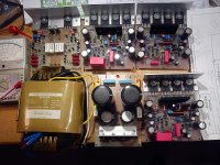
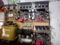
Finally I have all needed parts to start to assemble my two box TT amps to drive Orion loudspeakers. This is just for one Orion, three power amps with power supply.
Very nice! What have you been up to lately?
Very nice! What have you been up to lately?
Hi Mason, look here: http://www.diyaudio.com/forums/solid-state/235695-no-nfb-line-amp-gainwire-mk2-24.html#post3797899
Long time no news from you. TT amp still in use?
Damir,
Very nice! I notice you're offering PCBs; I would jump on-board, although I don't have time to build one myself at the moment. Too many "irons in the fire."
Long time no news from you. TT amp still in use?
Yes, TT amp is still alive and well. Have you updated the PCB layout/design since we last corresponded?
Last I heard ThermalTrak's were discontinued; do you know if this is true?
I've been getting myself into guitar DIY electronics - guitar pedals and amplifiers. The guitar is an interesting design problem, in many ways the complete opposite of hi-fi. The goal is to make pleasing distortion tones rather than eliminate it!
I setup a website: Coming Soon - Home
I initially plan to offer my guitar pedal designs, and eventually make amps available: both tube and solid state if the business goes anywhere.
Damir,
Very nice! I notice you're offering PCBs; I would jump on-board, although I don't have time to build one myself at the moment. Too many "irons in the fire."
Yes, TT amp is still alive and well. Have you updated the PCB layout/design since we last corresponded?
Last I heard ThermalTrak's were discontinued; do you know if this is true?
I've been getting myself into guitar DIY electronics - guitar pedals and amplifiers. The guitar is an interesting design problem, in many ways the complete opposite of hi-fi. The goal is to make pleasing distortion tones rather than eliminate it!
I setup a website: Coming Soon - Home
I initially plan to offer my guitar pedal designs, and eventually make amps available: both tube and solid state if the business goes anywhere.
Nice, a long time ago I did some guitar amps, first tube then SS. Different requirement, depends for what guitar, bass, rhythm, or solo, you need different resonances, and also distorters, whah-whah(or how it was called), vibrato, echo ... . That was very nice time, I was young and played bass guitar for some time.
I did not check TT transistor availability, I still have some spare.
BR Damir
OnSemi continues to offer ThermalTrak transistors. I don't know why the rumor existed that the line was being discontinued or cut back.
It's not a rumor. They already are retiring the 21193/4 and also the 4281/4302 types. It's a pitty, they could've kept at least the top of the line types.
Perhaps they are not selling enough of them and they're reducing the number of references as a result.
They're working against themselves. Retiring parts before they have time to be adopted won't make them sell. Now because certain models are being retired, those aren't selling because nobody wants to get what won't be available later for repairs.
OnSemi continues to offer ThermalTrak transistors. I don't know why the rumor existed that the line was being discontinued or cut back.
Yes, I just received remaining sample last month...it was order early last year and almost a year they served so this indicates that they produce again thermaltrak devices.
I really though that they stop production since they don t served all my request for thermaltak but lately it comes...
As I understand the NJW1302 has the same die as the MJL1302, minus the diode.
That's an idea I've had about using the diodes for something else. What can you use the diodes for that's not for thermal compensation? I suppose you could use them in a direct thermal protection circuit rather than a VI limiter, and this might increase the useful power. You could also wire them to a needle meter to directly show the "stress" of the amplifier. If you were clever you could use them both for compensation and for measuring stress.
That's an idea I've had about using the diodes for something else. What can you use the diodes for that's not for thermal compensation? I suppose you could use them in a direct thermal protection circuit rather than a VI limiter, and this might increase the useful power. You could also wire them to a needle meter to directly show the "stress" of the amplifier. If you were clever you could use them both for compensation and for measuring stress.
As I understand the NJW1302 has the same die as the MJL1302, minus the diode.
That's an idea I've had about using the diodes for something else. What can you use the diodes for that's not for thermal compensation? I suppose you could use them in a direct thermal protection circuit rather than a VI limiter, and this might increase the useful power. You could also wire them to a needle meter to directly show the "stress" of the amplifier. If you were clever you could use them both for compensation and for measuring stress.
I was thinking in the same line, to use one of TT diode for the heath sink temperature indicator. A opto coupler could be used if no free TT diode available.
Direct thermal protection could be to slow in case of the output short connection.
There so many ideas to play with and I am not young any more(getting 70 next mouth), other things occupied me too(grand children, a house, garden, never had less time then now in retirement). Kean, you are young and talented, you could do many things and show us here.
Damir
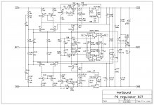
Hi ThimiosHi dear Damir ,can you tell me the max current this power-protection supply can produce?
Thimios.
As showed in the schematic, about 12 A, the current sensing resistors R9 and R109 are made from two parallel 0.22R 5 W resistors. The trick is that that the max current is a transient dependent, shorter the current pulse higher is the current trigger point. If I remember correctly my simulation(it was two years ago) the trigger point varies from 10 to 15 A, higher for shorter pulse. As the voltage drop on the serial transistor is about 6 V, it's easy to calculate dissipated power on that transistor at different currents. Average power dissipation in the PS regulator is quite low, except if listening rock music very loud prolong period.
Current limit could be easily changed by changing the value of the sensing current resistors.
BR Damir
- Status
- This old topic is closed. If you want to reopen this topic, contact a moderator using the "Report Post" button.
- Home
- Amplifiers
- Solid State
- ThermalTrak+TMC amp