I was referred here from a post on AVS. As I look around this forum, I can tell I am out of my league. But I have a problem that hopefully you guys can help me out with.
I have a Proceed HPA 3 that has died. About 5 years ago I had a similar card failure and sent it off to be repaired. The repair was completed and all was well until this weekend. Had the same failure as before. The unit powers up for a second then goes into self protect mode. I isolated the bad board down to the center channel.
Before I do anything else I would like to try and fix this myself.
I have also checked all of the resistors and believe they are good. Except for two components that look like resistors to me, especially because of the way they are marked. One is black, the other white.
I have taken some pictures of the bad board and of the board that was repaired earlier. If I visually compare the two boards, it is apparent that the repair shop simply added a new component over the old one. The shop used the same replacement component for both of the failed components. It is labeled:
TRC LF
8k 66 1%
The pictures below show the old versus new for the two components.
The white component is a:
CP-5 Mexico 9913
1.8K OHM 5% Dale 5W
And the black one is a:
IRC
2k74 TO
9849
Repaired board:
Bad Board
Repaired white component
Repaired black comonent
What I would like to do is get some help in determining what the correct replacement parts are and where to order them.
I will then use my meager soldering skills and try to make the same repair as the previous repair and see if I can get this amp working again.
Am I crazy to try this, or should I turn this amp into a boat anchor?
I do not claim to be electronically inclined, but want to try and fix this problem. I also have a Proceed Amp 5 that has crapped out as well, but that is for another time. So let loose with any questions or criticisms, as I would like to see if I can power up this heavy amp.
This last picture is of the bad component showing what looks to be some discoloration due to excessive heat (As in it let the smoke out
__________________
I have a Proceed HPA 3 that has died. About 5 years ago I had a similar card failure and sent it off to be repaired. The repair was completed and all was well until this weekend. Had the same failure as before. The unit powers up for a second then goes into self protect mode. I isolated the bad board down to the center channel.
An externally hosted image should be here but it was not working when we last tested it.
Before I do anything else I would like to try and fix this myself.
I have also checked all of the resistors and believe they are good. Except for two components that look like resistors to me, especially because of the way they are marked. One is black, the other white.
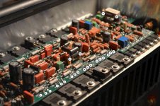
I have taken some pictures of the bad board and of the board that was repaired earlier. If I visually compare the two boards, it is apparent that the repair shop simply added a new component over the old one. The shop used the same replacement component for both of the failed components. It is labeled:
TRC LF
8k 66 1%
The pictures below show the old versus new for the two components.
The white component is a:
CP-5 Mexico 9913
1.8K OHM 5% Dale 5W
And the black one is a:
IRC
2k74 TO
9849
Repaired board:
An externally hosted image should be here but it was not working when we last tested it.
Bad Board
An externally hosted image should be here but it was not working when we last tested it.
Repaired white component
An externally hosted image should be here but it was not working when we last tested it.
Repaired black comonent
An externally hosted image should be here but it was not working when we last tested it.
What I would like to do is get some help in determining what the correct replacement parts are and where to order them.
I will then use my meager soldering skills and try to make the same repair as the previous repair and see if I can get this amp working again.
Am I crazy to try this, or should I turn this amp into a boat anchor?
I do not claim to be electronically inclined, but want to try and fix this problem. I also have a Proceed Amp 5 that has crapped out as well, but that is for another time. So let loose with any questions or criticisms, as I would like to see if I can power up this heavy amp.
This last picture is of the bad component showing what looks to be some discoloration due to excessive heat (As in it let the smoke out
An externally hosted image should be here but it was not working when we last tested it.
)An externally hosted image should be here but it was not working when we last tested it.
__________________
I couldn't find any schematics or service manuals for your amp - although you might be able to request a reprint from the Mark Levinson site if you explain your situation - MarkLevinson - Home
What I suggest when I have a known good example to compare to is to:
1) Sit the two PWB's next to each other and break out a BIG notepad.
2) Make point to point resistance measurements and compare the good board with the bad board.
3) Voltage checks will help - but you will need to get the bad board to give up that nasty smoking habit first - and for some - it's hard for 'em to quit!
Note - without a schematic taking a digital photo of the board and doing a printout that you can label the test points on can work pretty good. Not as well as a circuit diagram - but it might be enough to get you there.
Hope that you find this of at least some help........
Without a schematic, you will only be able to fix the problem if it is rather simple. You have a couple of suspect parts, and you need to test them. It is very important that you remove them from the board before doing this.
Removing parts from a surface mount board is very easy, but you need to know how before you try, or you could muck it up. There are many good videos on youtube that will show you how - search for "desoldering". You probably want to use desoldering braid, rather than a desoldering pump. Check out a few videos, and you will see how little skill is needed. Test the parts once you have them out. Once you do that, post your results on this thread, and Ill help you plot your next move.
Removing parts from a surface mount board is very easy, but you need to know how before you try, or you could muck it up. There are many good videos on youtube that will show you how - search for "desoldering". You probably want to use desoldering braid, rather than a desoldering pump. Check out a few videos, and you will see how little skill is needed. Test the parts once you have them out. Once you do that, post your results on this thread, and Ill help you plot your next move.
Hi jacketfan,
Replacing the resistors may not help if you don't check the
output transistors for short or open and other parts.Time to learn to use a multimeter.
There is one important observation and that is the black resistor being
used to replace the 5W white ceramic resistor.From the size ,it is too small
even if it is the same value.I'm surprised it did not burn out but maybe the
technician readjusted to a lower bias.A dirty trick no less.
Some of the resistors are 1% tolerance,so you may have difficulty
finding them in big wattage of 1 to 2 watt but in all case you can substitute 5% types but of course the circuit will drift a bit. Best of luck.
Discharge the power caps before you go in with a suitable 5-10W resistor
of 1 K ohm or more to ground and measure the residual voltage left at the
caps to check if they are fully discharged. singa.
Last edited:
Hi
If you're lucky, the same components have failed as last time. That would make it a lot simpler. The black and white components do look like resistors. Have you measured them and compared to the same components on another good board?
Don't compare to the previously repaired one though, since that got patched up with wrong-valued parts anyway. You can test with a multimeter set to "resistance". It's best to measure each component both ways around as you might get different answers depending what else they're connected to.
That's a good enough reason to be here. Welcome to the forum.As I look around this forum, I can tell I am out of my league...
Agreed about the under-sized replacement. Oddly enough it's quite a high value though (1.8K), so obviously not for bias stabilization. Maybe part of the feedback network, which would make such a lousy repair doubly diabolical.There is one important observation and that is the black resistor being used to replace the 5W white ceramic resistor.From the size ,it is too small even if it is the same value.I'm surprised it did not burn out but maybe the technician readjusted to a lower bias.A dirty trick no less.
On the up-side, the OP's probably already better qualified to work on the amp than the last guy who fixed it.
(Hey, at least he bothered to look at the writing on the components)Gentlemen,
I greatly appreciate your assistance. c2thomas, I appreciate your reference to a smoking habit. I have let the smoke out of way to many things electrical.
I have a email in to Harman, and I also searched for circuit diagrams. I suspect, Harman may be reluctant to provide such information.
My background is in Aerospace Engineering, so I have some familiarity with electronics, but by no means consider myself anything but a newbie at this. The best I have done is speaker crossovers and a LT circuit for a subwoofer.
I have ordered replacement resistors and will give that a shot by replacing the two resistors that were bad on the "bad" board.
I have a cheap multimeter, so if there is anything else I need, let me know and I will add to the tool collection.
As far as desolering, I am not sure I have the skills to remove the board from the heat sink. So my plan right now is to do the same sort of cheezy fix the bozo that did the previous fix did.
I will update if I get anything from Harman and when I get the resistors redone.
This amp has been powering Maggie 3.6s for quite a few years now, and I would like to continue.
Thanks again for your assistance,
Mark
How about clipping off the old components, then soldering the new ones to what's left of the old component's leads? It's not perfect, but better than the previous job - at least you're getting the "dead" stuff out of the circuit. Remember, it may only be half-dead.So my plan right now is to do the same sort of cheezy fix the bozo that did the previous fix did.
Hi Mark - when I said take a photo and insert some test points on it I intended something like the attached photo.
Mark it up (no pun intended) and then on the note pad record your findings.
Next up on test equipment to acquire would be a o'scope and audio signal generator IF you really want to get into the building electronics side of this hobby. Not really worth the price of admission unless you plan to get some usage outta 'em tho.
Mark it up (no pun intended)
and then on the note pad record your findings.Next up on test equipment to acquire would be a o'scope and audio signal generator IF you really want to get into the building electronics side of this hobby. Not really worth the price of admission unless you plan to get some usage outta 'em tho.
Attachments
Last edited:
I have ordered replacement resistors and will give that a shot by replacing the two resistors that were bad on the "bad" board.
I have a cheap multimeter, so if there is anything else I need, let me know and I will add to the tool collection.
As far as desolering, I am not sure I have the skills to remove the board from the heat sink. So my plan right now is to do the same sort of cheezy fix the bozo that did the previous fix did.
How are your soldering and de-soldering skills? I can offer some links to some "how to" sites - buuuuuuuuuut to get goooooooood it takes practice.
Hi jacketfan,
Another tip is I noticed that the pcb is dusty,if it's only the
resistors(which I doubt) and the wrong value resistor perhaps a good cleaning with a small paint brush will help and for heavy duty I normally use a vacuum cleaner.
Dust can cause shorts when moisture mixed with the dust on solder joints.
Singa
Is there anything worse than an intermittent electrical problem?
I was following ya’lls recommendations and was checking resistance again. The two resistors I am about 90% certain were open, tested good. I put the “bad” card back in the amp and powered it back up.
I will be cussed. It did not shut down. It was late and I had another speaker building project going, so I unplugged the amp.
Now I question whether I measured those as open or not. If so, what could have happened for resistors to heal themselves?
Crap, this is frustrating.
Will do some more investigation tonight.
singa, I will clean up the dust. The amp has been in the theater room since 2006, and has been in my shop area of the basement for a couple of days.
Hi jacketfan,
It's quite possible that after long period of time like years,
the oxidation of component leads have a layer of "insulation" when that
happens I will scrape off the surface or use the sharp meter probes to scratch
the leads and really make sure that there is contact between probe and lead
surface or any other surface like transistor leads so error readings are reduced. Singa
It's quite possible that after long period of time like years,
the oxidation of component leads have a layer of "insulation" when that
happens I will scrape off the surface or use the sharp meter probes to scratch
the leads and really make sure that there is contact between probe and lead
surface or any other surface like transistor leads so error readings are reduced.
SingaIs there anything worse than an intermittent electrical problem?
I was following ya’lls recommendations and was checking resistance again. The two resistors I am about 90% certain were open, tested good. I put the “bad” card back in the amp and powered it back up.
I will be cussed. It did not shut down. It was late and I had another speaker building project going, so I unplugged the amp.
Now I question whether I measured those as open or not. If so, what could have happened for resistors to heal themselves?
Crap, this is frustrating.
Will do some more investigation tonight.
singa, I will clean up the dust. The amp has been in the theater room since 2006, and has been in my shop area of the basement for a couple of days.
Bah - intermittent electronics problems - those can indeed be a real biiiitch. Loose connections, thermal breakdown causing opens or shorts (usually opens) oxidation, bad solder joints, ------- the list goes on. Tools of the trade = cans of freeze spray - heat guns - vibration (i.e. banging on 'em with your tool of choice) when in doubt - resolder suspected joints.
Work and travel keep interrupting my efforts in trouble shooting this amp. I am also trying to trouble shoot a Proceed Amp 5 that does not work as well.
I had previously reported putting the card back in the chassis and not getting the same failure. I had not connected the card to the speaker terminals, and when I did the amp went back to the previous failure.
I also got a response to an email I sent to Harman that I included below:
From me to Harman:
I have an HPA3 that has failed for the second time. I had a board repaired by a repair shop out in Texas, that as shown in the following thread, he may not have been qualified to do a professional repair. It has been a couple of years and I have no contact information, but he did a real hack job on his repair. But that is not what this is about.
The reference thread I posted on the diyaudio forum, and they suggested I contact Harman to see if you would supply a circuit diagram of the board.
http://www.diyaudio.com/forums/solid-state/182272-gentle-first-time-poster-problem-proceed-amp.html
I would like to repair the amp, and believe that with a reference to the previously failed board and the help of the enthusiast on the forum, I can get the amp usable again.
I initially had a Lexicon MC-12B and the HPA3 with an Amp5. The amp 5 also died and has been sitting in the basement for about 4 years. I must be bad news for Proceed amps. The replacement amps, a Cinepro and an Adcom have served admirably in replacement. I guess if it is possible, a circuit diagram of the Amp 5 cards may motivate me to try the Amp 5 as well. But I really do want to fix the HPA3 which powers my Maggie 3.6s.
Thanks for your consideration in this matter,
Second email:
Richard,
Glad to know you support your service centers, and the change is correct.
1) Does that mean the existing boards need the same fix and they are just waiting to fail as well?
2) Is there a way to get support in trying to troubleshoot and fix these amps? Especially on how to discharge the capacitors so that I don’t light myself up?
3) Any sort of fix required to the Amp 5?
Harman’s response:
Basically the response was that they are not staffed to help with any trouble shooting and the repair is correct. No help from Harman. Not even on how to properly discharge the capacitors.
There are two areas on the board which have discolored parts.
I have started to recheck and record resistance of each resistor.
Unless it is a resistor, I have no clue on how to check the other components on the board.
What are the steps you would recommend on trouble shooting?
This post is pretty old - but you might try Kevin and see if he still has contact with Christopher.
Proceed amp died - any advice? [Text View] - AVS Forum
"Kevin C Brown
10-15-07, 09:26 PM
Finally, I did hear back from the dude I crossed paths with before. I'll just post his response word for word:
Ok, I read the post and this is very common. I do know what the problem is,
and I have the schematics and parts that he needs. But unless he is good
with electronics there is no way he could repair it without making it worse.
If he wants to send it to me I'll do it for 200 plus shipping. My cell is
currently at the bottom of Portland harbor in the UK so just email me back.
Thank You,
Christopher Q. Taddei
Bluefin Robotics Corporation
Marine Operations Engineer
Work Cell (781)249-7577
CTaddei@Bluefinrobotics.com
fwiw"
Finding the defective component without a service manual and schematic is a challenge - but it can be done. Getting the amp up and running without knowing the bias settings and which voltages to check etc. is asking for trouble unless you are very familiar with the unit.
Proceed amp died - any advice? [Text View] - AVS Forum
"Kevin C Brown
10-15-07, 09:26 PM
Finally, I did hear back from the dude I crossed paths with before. I'll just post his response word for word:
Ok, I read the post and this is very common. I do know what the problem is,
and I have the schematics and parts that he needs. But unless he is good
with electronics there is no way he could repair it without making it worse.
If he wants to send it to me I'll do it for 200 plus shipping. My cell is
currently at the bottom of Portland harbor in the UK so just email me back.
Thank You,
Christopher Q. Taddei
Bluefin Robotics Corporation
Marine Operations Engineer
Work Cell (781)249-7577
CTaddei@Bluefinrobotics.com
fwiw
"Finding the defective component without a service manual and schematic is a challenge - but it can be done. Getting the amp up and running without knowing the bias settings and which voltages to check etc. is asking for trouble unless you are very familiar with the unit.
Oh, c2cthomas, you bring back some dreadful memories. I am "jacket_fan" that started that post. Thanks for finding that post though.
It is amazing how heavy these amps are. I belive they are both over 100 lbs each.
I believe it is something simple, and would like to give it a try to see if I can find a solution.
It is amazing how heavy these amps are. I belive they are both over 100 lbs each.
I believe it is something simple, and would like to give it a try to see if I can find a solution.
I finally found the email I had when I had the first bad card repaired. Here is what was reproted to have benn done.
THE DC servo op-amp failed. We replaced the AD805 with an LT1097. Other parts with a history were replaced.
I dont know the exact freight cost, probably $25, the repair was $300, so total ~$325.
I found on the card a opamp that is a AD805 on the old board and LT1097 on the repaired board.
I am not sure if you can tell from the pictures, but can you remove and replace that opamp without removing the board from the heat sink?
I know you guys have mentioned desoldering, but can you do that from the component side of a circuit board?
THE DC servo op-amp failed. We replaced the AD805 with an LT1097. Other parts with a history were replaced.
I dont know the exact freight cost, probably $25, the repair was $300, so total ~$325.
I found on the card a opamp that is a AD805 on the old board and LT1097 on the repaired board.
An externally hosted image should be here but it was not working when we last tested it.
An externally hosted image should be here but it was not working when we last tested it.
I am not sure if you can tell from the pictures, but can you remove and replace that opamp without removing the board from the heat sink?
I know you guys have mentioned desoldering, but can you do that from the component side of a circuit board?
No is the quick answer ... it looks like double sided print and requires extreme care working on it. To DIY remove an opamp would require snipping each lead as close to the body as possible... actually you could then solder a new one on top, but that's unprofessional... and then remove and clear the holes individually. Believe me, it's not easy as the hole is probably a plated through "via" which makes removing the solder difficult.
Are you sure the opamp is duff... they are usually supremely reliable and unless a fault puts an overvoltage on it it would be the last suspect tbh.
... it looks like double sided print and requires extreme care working on it. To DIY remove an opamp would require snipping each lead as close to the body as possible... actually you could then solder a new one on top, but that's unprofessional... and then remove and clear the holes individually. Believe me, it's not easy as the hole is probably a plated through "via" which makes removing the solder difficult.Are you sure the opamp is duff... they are usually supremely reliable and unless a fault puts an overvoltage on it it would be the last suspect tbh.
- Home
- Amplifiers
- Solid State
- Be gentle - first time poster with a problem with a Proceed amp