Hey guys, I really need some help or at least a hint from you.
I know basic electronics, but not enough.
Short story long: I picked up a HARMAN KARDON AVR230 from a thrift store for a bargain price. I tested front outputs and everything seemed fine, so I guessed all was OK. Big mistake!
At home I realise that no matter what setting I make, the rear outputs and center don't work at all. Only front ones and rear center. I will attach some pics so you can make an idea about what I am talking about.
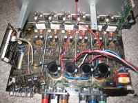
This receiver has outputs grouped in 2 groups of 3 outputs. The left group is working, the right is not. All 3 channels from that group are dead.
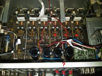
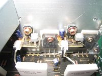
I opened the receiver and I noticed six rows of similar components. Right 3 rows are not working. I figured out some fuses were involved and upon checking I found 2 x 6.3A fuses blown. I replaced them and upon powering up both fuses blew again. I disconnected the transformer output for those fuses and replaced the fuses again. Upon powering up fuses remained intact. So whatever it is is on the mainboard in the 3 right rows-marked with an red x. The O1 output is the transformer output which seems to power up those rows.
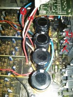
I can't check the voltage with the transformer output on because fuses are blown. If I disconnect both transformer outputs,O1 and O2 , readings from the non-working channels have a much lower voltage. Checking the power transistors with a voltmeter on diode checking between colector and motherboard are similar for all 6 channels. I don't see any leaking capacitors or blown transistors. I don't know what to check and where to start from. Whatever it is, it shorts all 3 outputs, which is weird and I think it has to be something those 3 outputs have in common, maybe the oversized capacitors?
Any input would be appreciated.
Thank you.
I know basic electronics, but not enough.
Short story long: I picked up a HARMAN KARDON AVR230 from a thrift store for a bargain price. I tested front outputs and everything seemed fine, so I guessed all was OK. Big mistake!
At home I realise that no matter what setting I make, the rear outputs and center don't work at all. Only front ones and rear center. I will attach some pics so you can make an idea about what I am talking about.
This receiver has outputs grouped in 2 groups of 3 outputs. The left group is working, the right is not. All 3 channels from that group are dead.
I opened the receiver and I noticed six rows of similar components. Right 3 rows are not working. I figured out some fuses were involved and upon checking I found 2 x 6.3A fuses blown. I replaced them and upon powering up both fuses blew again. I disconnected the transformer output for those fuses and replaced the fuses again. Upon powering up fuses remained intact. So whatever it is is on the mainboard in the 3 right rows-marked with an red x. The O1 output is the transformer output which seems to power up those rows.
I can't check the voltage with the transformer output on because fuses are blown. If I disconnect both transformer outputs,O1 and O2 , readings from the non-working channels have a much lower voltage. Checking the power transistors with a voltmeter on diode checking between colector and motherboard are similar for all 6 channels. I don't see any leaking capacitors or blown transistors. I don't know what to check and where to start from. Whatever it is, it shorts all 3 outputs, which is weird and I think it has to be something those 3 outputs have in common, maybe the oversized capacitors?
Any input would be appreciated.
Thank you.
Attachments
Last edited:
Aucosticraft - Somehow i doubt a firmware problem is blowing fuses!!
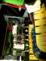
aghory, I can't tell from the pictures but they must be in pairs somehow. You might have to look at the underside of the PCB and figure it out from the traces.
IT actually looks like some of the transistors are "upside down" and underneath the PCB, but i cant tell for sure from those pictures
aghory, I can't tell from the pictures but they must be in pairs somehow. You might have to look at the underside of the PCB and figure it out from the traces.
IT actually looks like some of the transistors are "upside down" and underneath the PCB, but i cant tell for sure from those pictures
Yes Jacyee firmware problem might rank lowest to create fuse blowing problem. but as there are just lot of problems with firmware. I asked you to do that. so that when you repair actual problem. you would be sure that firmware is not causing any errick behavior. to blow them again.
I am trying to find its schematic. so I can tell you repair and diagnostic steps.
I am trying to find its schematic. so I can tell you repair and diagnostic steps.
I took out the board. Indeed, there are another transistors on the rear. What do you suggest next, pulling them out or checking them on the board in some way?
Thank you
Thank you
Attachments
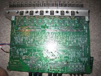
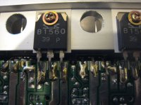
These will be in pairs - a 2SB1560 and 2SD2390 per channel. You will need to desolder all 3 pins on each transistor to test. Diode test between the center and right hand pins (collector and emitter), you should get conduction one way with a small voltage drop. If it conducts both ways reading a complete short, then the transistor has failed.
Thank you for your help, jaycee.
I desoldered all 6 transistors and upon testing them I found out that the most extreme left ones corresponding to the center channel act different from the other:they conduct current both ways and without any drop. That means I have a 2SD2390 and a 2SB1560. I found them online at B&d enterpris for 8.50 both. Now, do you think something else other than those 2 transistors can be affected? There are more transistors on that row and other parts, and even a smaller transistor on the same radiator. When the output transistors are shorted, usually something else is also shorted?
Another question...if I take out the transistors, the rest of the channels should work ?
Thank you
no, not short, maybe open.
You would have a look on those .27 ohm white resistors near your transistors. They are probably emitter resistor and can happen that they go burnt and open .If your transistors are already out, one leg of the resistors should be free, so you could just check them with ohm meter (you need low-ohm reading) in situ. If they are three-legged (double ones) two legs should go to transistors, one leg to the output, so you should measure 2 times 0.27 ohm referred to the output leg.
effebi
Last edited:

To help you a little on the way:
Here are the schematics
It is probarly more errors, work your way back from the protection output from the amp and you might find some.
Here are the schematics
It is probarly more errors, work your way back from the protection output from the amp and you might find some.
- Status
- This old topic is closed. If you want to reopen this topic, contact a moderator using the "Report Post" button.
- Home
- Amplifiers
- Solid State
- HARMAN KARDON AVR230 problem