yes its me again with yet another stupid question (at least i think so)
I have finally built one channel of the leach super amp, and dammit it works .
.
but i dont understand how to set the bias. I have read other peoples posts and some are setting it to 230 mA or so ???????. in the instructions im supposed to set the bias till my DC current draw reaches 100mA at the power entrance to the board (is this correct), but at this level i see 2 problems. the output transistors get ridiculously hot even when it is at idle. When looking at the output signal (no input or anything else connected but power) on the oscilloscope there is some sort of noise/distortion surrounding the flat line, if i turn it down to just below the threshold where the "noise" disappears the transistors run a lot cooler, but my draw drops to approx 30mA. what am i doing/not doing right
thank you once again for your help
I have finally built one channel of the leach super amp, and dammit it works
.but i dont understand how to set the bias. I have read other peoples posts and some are setting it to 230 mA or so ???????. in the instructions im supposed to set the bias till my DC current draw reaches 100mA at the power entrance to the board (is this correct), but at this level i see 2 problems. the output transistors get ridiculously hot even when it is at idle. When looking at the output signal (no input or anything else connected but power) on the oscilloscope there is some sort of noise/distortion surrounding the flat line, if i turn it down to just below the threshold where the "noise" disappears the transistors run a lot cooler, but my draw drops to approx 30mA. what am i doing/not doing right
thank you once again for your help
Is the behavior the same when the input is shorted? It sounds like you are either getting some RF into the front end or you have an oscillation issue.
Pictures of your layout would be useful
i havent tried shorting the input (im guessing you mean input signal to common ground) id love to send pics, but dont know how to put them up, or send them for that matter, is there an "attach" button i dont see on here
thanx!
Having designed my own amplifiers I use my own method for setting bias.
I apply a small sine wave and monitor the output.
I turn the bias right down to start with then increase it until crossover distortion disappears on the scope. This method means the setting is not too little you get crossover distortion but not so much the heat generated is wasted.
If the problem is oscillation you will see it on the output.
Last edited:
If you click on the "Go advanced" button there is an icon that looks like a couple mountains. That will insert a link to a picture you have uploaded to a website like photobucket or you can put in a link to your own website.
Down below in the additional options section is a button labeled Manage attachments.
Yes, connect the signal input to ground or connect it to a low impedance source as Nigel suggests. See if you can adjust the time base on your scope to find the frequency of the noise you see.
You may be seeing an oscillation due to lead length or dress. Another potential problem area is if the base stopper resistors are on the board and the leads to the bases of the output devices are more than an inch or so long. Better to mount them right on the base lead of the device.
manage attachments allows one to attach pics and diagrams to one's post.
If you upload your first 3 then you can repeat the process for a further 3 attachments.
Before you save them:
crop the pic to what you need us to see.
resize to as few pixels as allow us to see the details.
compress using an appropriate jpg, jpeg, png, compression system.
Then upload to DIYaudio.
Please do not use other servers. They are too slow and you eventually lose links.
output bias setting
measure the bias current across the output emitter resistor, all 4 should be within 10% of total range (20 to 22mV) .
Leach tells you the voltage/current to set for Re=0r33
The Iq measured at the supply rails is the total of all +ve (or -ve) output bias plus quiescent current of the voltage amp stage plus the driver and pre-driver bias currents, plus the output offset current (if any).
Short the input.
Leave the output open circuit.
Set bias and then check Iq (volts across 1r0) and output offset (mVolts) and output noise (mVac)
Check what happens when you switch ON and OFF. You don't want big pulses of current going to your speakers at ON/OFF
Connect your Source and recheck everything with the Source switched OFF and again with the Source switched ON.
Last edited:
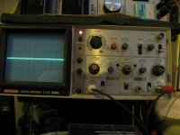
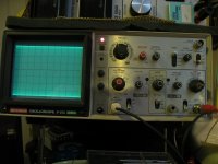
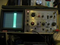
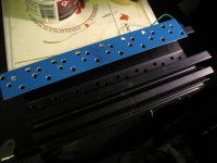
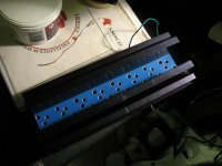
please excuse my horrific setup, but it is my first time, im nervous "tee hee"
1. the bias pot turned down
2. bias approx half way
3. time on scope slowed right down with bias at same level
(im reading from channel 2 if you can read my settings. (i really dont know how the hell to use that thing, but i understand it for the most part)
1. the bias pot turned down
2. bias approx half way
3. time on scope slowed right down with bias at same level
(im reading from channel 2 if you can read my settings. (i really dont know how the hell to use that thing, but i understand it for the most part)
Attachments
Last edited:
You want to turn the time base the other direction to see the waveform - this is a HF oscillation. Start @.2us and work your way down to see an entire waveform if possible.
Are your base stoppers on the board or at the output devices? Those long leads are likely contributing to instability. The lead inductance and the input capacitance of the output devices form an LC resonator. Having the resistors at the base of the output devices lowers the Q of the circuit helping to prevent oscillation. Make the leads as short as possible. What devices are you using? The original devices were slower than many modern replacements. Faster devices are more likely to oscillate.
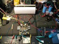
The only comment I have about your bench is clean up a bit to avoid accidentally contacting high voltage, whether that partially inserted mains plug on the left or the rail fuses on the right. We'd all love to have a bench that looks like a NASA clean room, but most look more like yours. Mine is often more cluttered.
Are your base stoppers on the board or at the output devices? Those long leads are likely contributing to instability. The lead inductance and the input capacitance of the output devices form an LC resonator. Having the resistors at the base of the output devices lowers the Q of the circuit helping to prevent oscillation. Make the leads as short as possible. What devices are you using? The original devices were slower than many modern replacements. Faster devices are more likely to oscillate.
The only comment I have about your bench is clean up a bit to avoid accidentally contacting high voltage, whether that partially inserted mains plug on the left or the rail fuses on the right. We'd all love to have a bench that looks like a NASA clean room, but most look more like yours. Mine is often more cluttered.
BobEllis thanx for the reply.
ok your talking a bit over my head lol. basically i followed the instructions to a "T" there are the (4) 0.33R resistors on the board and there are (4) more at the heatsinks (if thats what you mean by base stoppers), keep in mind this is just a temporary setup before i put it in the chassis. Im still using the MJ15003/4 outputs.
i get the same distortion at any scope speed, the pic i posted was at 1ms. but is the same at the top of the scale .2us
Am i taking my reading from the correct spot, +85vDC, the red aligator clip on the fuses on the right, to read for the "100mA"
yes, i know about my bench, what can i say i live life on the edge, it adds excitement lol
The base stoppers are the 10R connected to the bases of the output devices. R41-44 and R56-59 on Leach's original schematic.
If you are using your ammeter to replace one of the rail fuses, you are measuring the correct spot.
So you cannot see an individual waveform at 2 us/division? Your oscillation is >20 MHz your scope can handle. As it seems to start as soon as you apply enough bias to get the output stage going, I suspect its a base stopper issue. But verify that C9/10/11/26/27 are installed and of the correct value. If moving the base stopper resistors to the output devices doesn't stop the oscillation you may want to try increasing C10/C11 to 39 pf.
Nigel and Andrew, any other suggestions?
Looking at your scope, I noticed that you selected external trigger, but have nothing connected. If you use internal trigger, you are triggering the sweep with channel 1 but you are using channel 2. Change that and see what happens. You can also use the line trigger position.
Keep your phone away from the test bench.
Keep your phone away from the test bench.
use your 2channel scope to display two signals.
The input signal on channel A and the output signal on channel B
First with just the input signal connected.
Adjust the vertical sensitivity until the sweep fills less than 100% of the screen and preferably more than 70% of the screen.
Then adjust the timebase (horizontal) until you see a clean sinewave. Stretch it out till you see only 2 cycles on the screen. A lot of other switches have to be set to achieve this. Learn how to get a steady two cycle display.
Now you are ready to connect the input signal to the amplifier and connect the output to channel B. Adjust channel B vertical sensitivity until the output signal is visible at a similar size to the input signal.
Be careful not to overload the scope nor the amplifier, while trying to get a steady display.
I use an accurate switched attenuator on the input signal. The attenuator is set to exactly the gain of the amplifier in the audio band.
The input to the attenuator is exactly the same voltage and the same frequency as the output from the amplifier.
This allows the channel A & B settings to be the same. Much more importantly you can use an inaccurate voltmeter to compare the input and output voltages. This allows you to check frequency respnse very accurately from 1Hz to 100kHz even though the voltmeter is virtually useless outside it's rated frequency range.
Comparison measurements are your friend. Use them, rather than trying to measure absolute values.
oh boy........... i feel like a donkey. I decided to re-trace all of my steps and start from square 1. thank you andrew & bob so much for your responses, but i think my only problem were the 10R & 0.01uFd cap to go in parralel with my speaker output, with that attached, my current stabilizes, the noise on the scope dissapears, the transistors run cool (until i crank it), and when i connect the speaker the current draw goes down, instead of up (im so glad you guys dont know where i am to throw things at me lol) Thank you guys once again for all your input, i really appreciate it. im going to keep fooling around with it until im 100%, then build the second channel. i can almost guarantee i will have more questions, so if you guys arent to sour at me i hope you can help me again!!
Cheers!!!!
Cheers!!!!
Glad you found it. Sorry I didn't think of looking at the output zobel. Try to shorten the leads to the output devices when you install your amps in the case.
I usually build all channels at once then test individually step by step. That way if one channel has a problem, I usually have at least one that works to help my troubleshooting.
BTW, you might want to watch what happens to the waveform as you adjust bias the way Nigel suggested to get optimum bias. Douglas Self has suggested ~0.025V across the emitter resistors is the optimum bias for BJT output stages. It might be a worthwhile test to see what bias level sounds best or what is the lowest bias that doesn't degrade sound quality. Nigel's method will probably produce the lowest bias setting, Self's the highest and the Leach method in the middle.
Your ears and speakers will determine the whether a bit more bias is worthwhile. I had reduced the bias on my modified Pass/Thagard A75 to quite a low level that appeared to have no crossover distortion and was quite happy with the sound. I was surprised to find that a crossover change using the same drivers/cabinet made that low bias setting unacceptable and I had to crank it back up quite a bit.
Keep your bias within your heat sink's limits, but that should be rather high with your fan even at reduced speed.
thanx again bob, i have just one more quick questiont that you should be able to answer, im using (2) wakefield 435 AAAA drilled for (4) TO3 per channel, do they need to be "thermally coupled". i made an aluminum plate that travelled in the channel between the transistors and the sinks to spread the heat, but i think it may be killing th efficiency of the sinks, can i ommit this piece without problem (i have the bias diodes divided 2X2)
Attachments
No, don't couple them that way unless you are going to lap the pieces to a near mirror finish. Read the articles (may be LowTIM) to see how to group the output devices and where to place thermal compensation diodes. I don't think it will be much of an issue even that your diode placement differs.
4 chimneys may allow you to go fanless for normal operation and have a thermal switch kick the fans on if the sink temperature gets to high. There is a thread about a two speed controller that looks interesting.
4 chimneys may allow you to go fanless for normal operation and have a thermal switch kick the fans on if the sink temperature gets to high. There is a thread about a two speed controller that looks interesting.
Last edited:
- Status
- This old topic is closed. If you want to reopen this topic, contact a moderator using the "Report Post" button.
- Home
- Amplifiers
- Solid State
- bias in leach amp