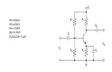
Be careful with the units; it is 40 (1/V) in the formula, so if you take Ic in amps, you get Gm in 1/ohm and Rpi in ohm. Milliamps will give you kiloohms, etc. You need to add R1 and R2 in parallel to the input resistance of the transistor to get the input impedance of the circuit.
Last edited:
Homework?
Looks that way. And fortunately, no one has given a fully correct answer.
hint: the answer is frequency dependent...
Should there be a term to represent the effect of Re//Rc has on the input impedance?
Rc should give that frequency dependence.hint: the answer is frequency dependent...
Unless you mean the effect of the DC blocking capacitor.
hint: the answer is frequency dependent...
We're only interested in the range where the amplifier is going to be operated, so other than calculating and noting the lower cut-off frequency for all practical purposes the value can be taken as R1||R2||hfe*re.
Should we ask whether the OP is looking for a first-year or second-year answer?
No. We should expect that if the OP knew the first-year answer he would have couched the question to show that.
w
Sorry. We get a lot of students popping up and asking questions. Very few of them make it clear, until we ask, that this is an assignment. Fortunately there are often clues for us to spot.
The particular question you raise is sufficiently simple that giving a clue and answering the question are almost the same thing. Clues involve algebra, and answers involve arithmetic.
It would be helpful to you in your education if you told us what you understand about this circuit, and what you are puzzling over. Then we can explain things. Simply asking for a clue as to how to answer the question suggests that your aim is not education but gaining marks. So tell us what you need to know. It is almost certainly already in your textbook or lecture notes, but we can point you in the right direction.
Don't get me wrong, I am not trying to copy anyone's work. I am looking for someone to show me how to do it.
In order to understand this, or any other, circuit that is implemented with BJTs, you need to understand that BJTs are unusual critters. What is going on at the emitter has definite effects on what happens at the base. And vice versa. This is in distinct contrast to vacuum tubes, FETs of all sorts, and IGBTs. Always remember: Ie= Ic + Ib
That's the key.
Now, assuming you're not looking for any sort of frequency dependence, and that your emitter is fully bypassed at the frequencies of interest, then:
re= 26 / Ie (Where Ie is in milliamps)
This will reflect into the base as:
hie= re(1 + Hfe)
(Or you can figure it: hie= 26E-3 / Ib) (Where Ib is in amps)
Now you have those bias resistors to account for. Here, the DC rail is considered to be sitting at AC ground, since any decent power supply will theoretically have no AC appearing across it. That doesn't happen IRL, but you can come close enough for all practical purposes.
The bias resistors appear in parallel, so far as the signal source is concerned. Therefore:
Zi= R1 || R2 || hie
Frequency dependent behaviour at the low frequency end will be determined by the emitter bypass capacitor, the coupling capacitors, and the frequency(ies) where it(they) begins to lose effectiveness.
At the high end, you have internal device capacitance, Miller capacitance, and external stray capacitance. It will also probably involve the BJT's "Beta cutoff" frequency, since the gain will roll off at -6.0db(v) / octave above that frequency.
Does that help?
Last edited:
- Status
- This old topic is closed. If you want to reopen this topic, contact a moderator using the "Report Post" button.
- Home
- Amplifiers
- Solid State
- Calculation of input impedance (Common emitter amplifier)