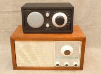
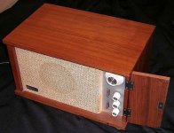
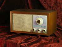
Tivoli Solid State Radio "Model ONE" vs. KLH Model 21 "TWENTY ONE"
Tivoli Model ONE vs. KLH Model TWENTY ONE
I need the schematic of Tivoli Model ONE. Who can help?
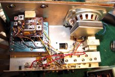
Here some URLs and attached pics - the KLH model 21 looks in much higher quality standart than Tivoli Model ONE - at least in the aera of the RF-IF unit (variable capacitor e. g.)
URLs to Tivoli Model ONE
http://www.diyaudio.com/forums/full-range/76959-tivoli-speaker.html
http://www.diyaudio.com/forums/parts/97391-tivoli-model-1-fm-aerial-connector-replacement.html
http://www.diyaudio.com/forums/parts/57858-tivoli-model-one-aux-input-modification.html
photos for albums/Audio/Tivoli Model 2
http://www.datasheetcatalog.org/datasheet/philips/TEA5710.pdf
URLs to KLH Model TWENTY ONE
klh model 21 with problems... - The Classic Speaker Pages Discussion Forums
The KLH Model 21 re-invented - Tivoli System Henry Kloss Model One AM/FM Radio ( Walnut) - Epinions.com
KLH Model 20 Plus - The Classic Speaker Pages Discussion Forums
Vintage KLH Model 21 AM/FM radio circa 1970's - eBay (item 260720654378 end time Jan-18-11 18:14:03 PST)
Tivoli Model ONE vs. KLH Model TWENTY ONE
I need the schematic of Tivoli Model ONE. Who can help?
Here some URLs and attached pics - the KLH model 21 looks in much higher quality standart than Tivoli Model ONE - at least in the aera of the RF-IF unit (variable capacitor e. g.)
URLs to Tivoli Model ONE
http://www.diyaudio.com/forums/full-range/76959-tivoli-speaker.html
http://www.diyaudio.com/forums/parts/97391-tivoli-model-1-fm-aerial-connector-replacement.html
http://www.diyaudio.com/forums/parts/57858-tivoli-model-one-aux-input-modification.html
photos for albums/Audio/Tivoli Model 2
http://www.datasheetcatalog.org/datasheet/philips/TEA5710.pdf
URLs to KLH Model TWENTY ONE
klh model 21 with problems... - The Classic Speaker Pages Discussion Forums
The KLH Model 21 re-invented - Tivoli System Henry Kloss Model One AM/FM Radio ( Walnut) - Epinions.com
KLH Model 20 Plus - The Classic Speaker Pages Discussion Forums
Vintage KLH Model 21 AM/FM radio circa 1970's - eBay (item 260720654378 end time Jan-18-11 18:14:03 PST)
Attachments
-
 KLH Mod TwentyOne21 Radio+Tivoli ONE Front.jpg72.4 KB · Views: 2,347
 -
 KLH Model 21 inside_after.jpg126.5 KB · Views: 2,278
 -
 KLH Model 21 operating aera open.JPG41.7 KB · Views: 2,201
 -
 KLH Model TWENTY ONE front.jpg673.8 KB · Views: 2,343
 -
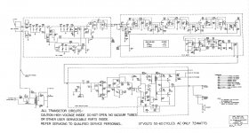 KLH Model TWENTY ONE schema.jpg199.8 KB · Views: 3,392
 -
 KLH Model TWENTY ONE SM.jpg4.7 KB · Views: 1,682
 -
 Tivoli Model ONE Variable capacitor.jpg75 KB · Views: 1,358
 -
 tivoli model one hf-rf-speaker.jpg82.1 KB · Views: 1,510
 -
Tivoli Model ONE-I inside.pdf60.3 KB · Views: 1,283
-
Tivoli Model ONE-II inside.pdf68.3 KB · Views: 853
Last edited:
Now I have my own schematic drawing - the main feature is the "feedforward correction" respective equalizing in front of the power amp input.
This contains no DSP technique but four analouge operational amplifier sections. Similar to
Pfleid Loudspeakers
but not similar to ace bass correction
Audio Pro - Sound of Scandinavia
After carried out repair work by some devices this service now is an easy task for me (only for Tivoli Model "ONE") - but only when I have several devices of the same model at the same time.
The measures frequency response has enhancements in the aera between approx. 100-200Hz so as between 11-14 KHz on axis (attenuated in great value off axis)
The medium range (midrange) arround 2-3 kHz is attenuated approximately 6db
Flicker noise while turn on by tuning select knob is the chief defect (internal contact trouble in the sliding contacts of variable capacitor/polyvaricon - after solder out and completely disass'y easy to clean - but first thing (so as the follow assembly procedure is too complicated as I suggest here this for normal technical persones.
Next Step is finding out a variable capacitor in same sizes, but only for FM (without AM). Then the reliabitity must be much more higher.
Must users don't need AM aera - so I think.
Last edited:
New capacitor for Tivoli one
After several years using this nice radio, the big problem associated to the tuning capacitor varycom emerged and is impossible to use FM .
I decided to transform it in one FM receiver using a classical and better air two gang capacitor ( 2x 20 pF). For the moment I will receive in a few days this unit VARIABLE CAPACITOR TWO GANG JACKSON BROS from Ebay and I will try to incorporate it in the box, non easy task due to the size.
Is there other alternative to find a better and compatible capacitor to maintain also AM band ? Any suggestion related to this modification is welcome .
I don't understand this term:After several years using this nice radio, the big problem associated to the tuning capacitor varycom emerged and is impossible to use FM .
I decided to transform it in one FM receiver using a classical and better air two gang capacitor ( 2x 20 pF). For the moment I will receive in a few days this unit VARIABLE CAPACITOR TWO GANG JACKSON BROS from Ebay and I will try to incorporate it in the box, non easy task due to the size.
Is there other alternative to find a better and compatible capacitor to maintain also AM band ? Any suggestion related to this modification is welcome .
"the big problem associated to the tuning capacitor varycom emerged and is impossible to use FM"
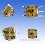
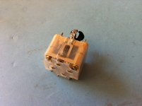
What exactly is the reason of the failure from your no longer useful variable capacitor?
Mean you the variable capacitor from image two of post #1? This kind of capacitor you will often find in various old fm tuner front ends, produced between 1960 and 1975.
Last edited:
In my opinion the varycom capacitor ( 160/ 80 pF for AM and 2x20pF for FM ) included in this radio receiver is not high quality and after 4-5years ( at least in my case ) is damaged , producing terrible noise during the tuning in FM . I do not know if the problem is associated to bad contact between the fixed plates and ground ( rotary axe ... ) or between plates . For the moment I am not considering other causes different to the capacitor.
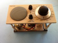
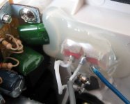
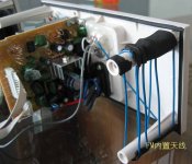
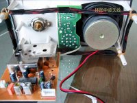
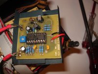
Hello Tiefbassuebert , yesterday I test only in FM my Tivoli One with a new variable capacitor 23+28 pF and is working perfectly without any noise during tuning. Is a little big as you can see in the photos but the diagnosis was correct.
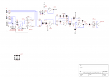
I have a big question concerning the schematic : following the pcb the pin 23 ( FM-Osc ) of TDA 5711T is connected to ground and the radio is operating with one single section of the capacitor .Do you agree with this conclusion and what should be the explanation ,not based in the product especification?
I have a big question concerning the schematic : following the pcb the pin 23 ( FM-Osc ) of TDA 5711T is connected to ground and the radio is operating with one single section of the capacitor .Do you agree with this conclusion and what should be the explanation ,not based in the product especification?
Attachments
I don't find the datasheet of the TDA5711T in the momentHello Tiefbassuebert , yesterday I test only in FM my Tivoli One with a new variable capacitor 23+28 pF and is working perfectly without any noise during tuning. Is a little big as you can see in the photos but the diagnosis was correct.
I have a big question concerning the schematic : following the pcb the pin 23 ( FM-Osc ) of TDA 5711T is connected to ground and the radio is operating with one single section of the capacitor .Do you agree with this conclusion and what should be the explanation ,not based in the product especification?
have a look to the datasheet of TDA5710T:
PIN23 am rf-I parallel tuned am arial circuit to GND
PIN18 FM OSC
Please do post the datasheet of TDA5711T or at least the application advices/schematic diagram
Attachments
Last edited:
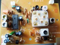
Sorry for the IC indicated , the correct IC used in the radio is Philips TEA5711T
http:// www.datasheetcatalog.org/datasheet/philips/TEA5711T.pdf
The real schema is not corresponding to the application note from this IC , being used one specific circuit for the RF front end with one dual gate FET ( U72 ) and other components ( SC 1359, 2N 3904, 2N 3906 ...)
With only FM , the radio is working very well with a new air variable capacitor -using one section- ( 10-30 pF), but in any case the modification is critical.
Attachments
Tivoli One: hiss and bad volume control
Has anyone found a schematic of the Tivoli type One?
Can't find it anywhere. Problem is hiss and bad volume control for low volume. Seems to be too much gain in the pre-amp.
I found this old thread: Tivoli Radio Hiss (Amplifier gain issue?) - AudioKarma.org Home Audio Stereo Discussion Forums with a solution by skittelsen. He decreased the gain of the preamp by changing the feedback resistor. He changed two channels, maybe in a model Two. The described components are not the same (R37) and not to be found (R41) in my One .
So I'm looking for the right feedback resistor. Found two op-amps N5532.
Table radio: Sony HD tuner with a nice little Gainclone and something like a TB or Mark audio 4 inch full range. A little bigger than the Cambridge though. A lot less money than that curved plastic fantastic. No one mandated a table radio to sound , well like a table radio.
Sorry for the IC indicated , the correct IC used in the radio is Philips TEA5711T
http:// www.datasheetcatalog.org/datasheet/philips/TEA5711T.pdf
The real schema is not corresponding to the application note from this IC , being used one specific circuit for the RF front end with one dual gate FET ( U72 ) and other components ( SC 1359, 2N 3904, 2N 3906 ...)
With only FM , the radio is working very well with a new air variable capacitor -using one section- ( 10-30 pF), but in any case the modification is critical.
Great work - but very effortful.
I am looking for an easy method to remove the good known shortcomings/deficiencies (my post #2). This means the necessity of variable cap and volume control potentiometers, which have identical outline, but high quality, reliability and livetime.
Which parts I must order?
Thanks for advices in advance.
BTW - there are more threads in this case:
http://www.diyaudio.com/forums/solid-state/201525-help-me-identify-damage-tivoli-model-1-a.html
http://www.diyaudio.com/forums/full-range/53392-drivers-used-tivoli-model-one.html
http://www.diyaudio.com/forums/solid-state/203208-tivoli-model-one-internal-fuse.html
http://www.diyaudio.com/forums/powe...one-supply-overvoltage-where-look-repair.html
Last edited:
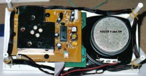
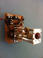
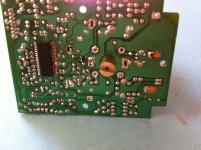
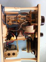
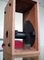
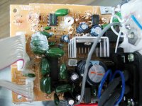
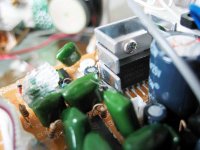
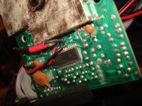
the kind of workmanship (partly cheap hot glue sealing at the component side) for me is absolutely poor and shoddy (cheap solid state radios from the 70s "Made in Taiwan" and "Made in Hongkong" showed here already significantly better standards).
In the attachment more images from the interiors.
Here more URLs, among other things for a conversion from 110VAC U.S. devices to 230VAC and circuit description:
Harry's radio's: september 2012 (include schematic)
Christians Homepage: Radioumbau, Quellenumschalter uvm.
Herculodge: Brian Pits His Sangean WR-11 Against His WR-1 and Tivoli Model One
Table Radio "Shootout" - Old Zenith vs. Tivoli One - AudioKarma.org Home Audio Stereo Discussion Forums
Who knows the name of the factory in China ??
Maybe to find here:
http://hkbbs.leowood.net:88/mini_read.asp?id=825241&page=3&property=0&ClassID=1
perhaps one of the members from this country would translate this for us.
Attachments
-
 Tivoli Model ONE inside-VII.JPG83.3 KB · Views: 648
 -
 Tivoli Model ONE inside-VI.JPG48.8 KB · Views: 515
 -
 Tivoli Model ONE inside-V.JPG69 KB · Views: 856
 -
 Tivoli Model ONE inside-IV.JPG82.4 KB · Views: 905
 -
 Tivoli Model ONE inside-III TDA7266.JPG58.9 KB · Views: 913
 -
 Tivoli Model ONE inside-II.JPG70 KB · Views: 924
 -
 Tivoli Model ONE inside-I.JPG84.5 KB · Views: 996
 -
 Tivoli PAL schematic.png19 KB · Views: 790
 -
 Tivoli TEA5711T high resolution.jpg442.9 KB · Views: 685
 -
 Tivoli Model ONE upgrade from claessonedwards.com.jpg455.8 KB · Views: 558
Last edited:
No news?
CONSUMER ELECTRONICS REVIEW
Kloss Model One vs CSW Model 88 & Bose Wave
Geek.com Consumer Electronics Review: Table Radio Showdown: Kloss Model One, CSW Model 88, Bose Wave
CONSUMER ELECTRONICS REVIEW
Kloss Model One vs CSW Model 88 & Bose Wave
Geek.com Consumer Electronics Review: Table Radio Showdown: Kloss Model One, CSW Model 88, Bose Wave
Dear TiefBassUbuertr,
I have Model One radio and observe the same problem as panxtiv described. The variable capacitor seem to be faulty and FM tuning is nightmare.
Can you please advise the part number for the original capacitor? or at least the range of capacity so I can find the corrsponding replacement (I dont want to remove the original one before I dont have the exact replacement - so the down time of the radio can be as short as re-soldering of the capacitor.
Thank you in advance
Hello to everybody,
I (from Germany) have the common trouble with the variable capacitor in my Tivoli-Two (stereo version). It makes the well-known noise after a couple of years probably caused by dust. Several times I was successful in repairing by dealing it with tuner spray. But now it is not possible anymore. On top of everything (after the last treatment with tuner spray) the (four-legged) FET (U72) has been damaged. I would be very thankful if anybody can help me with 1.) the general markings of these components, 2.) the data, or 3.) a distributor
Many thanks for any help in advance!
Wolfgang
Dear TiefBassUbuertr,
I have Model One radio and observe the same problem as panxtiv described. The variable capacitor seem to be faulty and FM tuning is nightmare.
Can you please advise the part number for the original capacitor? or at least the range of capacity so I can find the corrsponding replacement (I dont want to remove the original one before I dont have the exact replacement - so the down time of the radio can be as short as re-soldering of the capacitor.
Thank you in advance
The part number for the original variable capacitor is only to receive from the (me unknown) manufacturer in China. The German distributor inform me, that only the whole radio PCB exist as replacement part.
Disadvantage is here, that the same unwanted effects while fm tuning rises up after a short time of use.
- Home
- Amplifiers
- Solid State
- Tivoli Model ONE vs. KLH Model TWENTY ONE