
Just be careful John and check slowly
Gonna have to go... good luck.
Wow was my cam on?! Hahaha!
No worries Mooly - have a good evening
")
Well I took out the fuse for the 240V and inserted the bulb instead. I also took out the 110V fuse thinking it wasn't needed. Still looks correct from the circuit diagram...
I'll sleep on this one & wait for more of your wisdom tomorrow.
Ciao amigo
EDIT: Doh! Forgot that earth wire from the SMPS to the chassis as well. I'm leaving well alone for the evening now - obviously getting forgetful.
I'll sleep on this one & wait for more of your wisdom tomorrow.
Ciao amigo
EDIT: Doh! Forgot that earth wire from the SMPS to the chassis as well. I'm leaving well alone for the evening now - obviously getting forgetful.
Last edited:
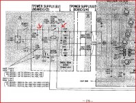
Fuses... look at the circuit here which I think was your version with the switchable selector.
F801 is for 240vac and this is the one we need to replace with a bulb for now.
As you say, F802 doesn't need be fitted at all for UK, and leaving it out is a safegaurd as then even if the selector were moved to 110vac nothing would happen.
So far so good then...
I was forgetting about the relay, R801 and the components R801 and R802 which are in series with a thermal fuse. As long as these are OK they don't affect anything so far.
When the amp is powered up these components act a bit like the bulb limiting initial current surge. Only when the DC output from the PSU appears does the relay close allowing shorting out these components and allowing full mains to appear.
Have you measured those resistors. Also the thermal fuse should read "short".
So there should be continuity of 4.4 ohms between the two arrows I marked.
Earth wire... we don't need it for this. All we need is the DC input to the SMPS in place.
So I think it's good to go. Make sure you are not touching anything on the PSU and that the PSU is not in contact with anything else.
Switch on... bulb should give a pulse of light and go out. If that's OK and no sign of heat/smoke or anything then switch off. Wait for the caps to discharge, give them a minute or so.
Next test is as mentioned to measure the DC volts across D601.
Attachments
Fuses... look at the circuit here which I think was your version with the switchable selector.
F801 is for 240vac and this is the one we need to replace with a bulb for now.
As you say, F802 doesn't need be fitted at all for UK, and leaving it out is a safegaurd as then even if the selector were moved to 110vac nothing would happen.
So far so good then...
I was forgetting about the relay, R801 and the components R801 and R802 which are in series with a thermal fuse. As long as these are OK they don't affect anything so far.
When the amp is powered up these components act a bit like the bulb limiting initial current surge. Only when the DC output from the PSU appears does the relay close allowing shorting out these components and allowing full mains to appear.
Have you measured those resistors. Also the thermal fuse should read "short".
So there should be continuity of 4.4 ohms between the two arrows I marked.
All checked and OK - everything set up exactly as your 2nd & 3rd paragraphs. Thermal fuse is brand new and measures short. Still nothing when I switch on - the relay doesn't click either on that small PSU board.
Does the output of the SMPS need to be connected up to the PSU board perhaps for it all to work? If the relay is powered by the initial DC from the PSU board the SMPS could remain powered even if a fault developed. If powered by the DC output from the SMPS it would provide a safey cut-off if problems developed, minimising damage. Wondering if there's a sort of 'safety loop' going on here, so if the SMPS developed a problem the relay on the PSU board would switch off?
Remember when I was using the external PSU - that was connected to the output points on the PSU board. And I heard the mains relay click each time power was applied then... In addition to the obvious G/B+/B- points on that PSU board, there are also several points marked in/out and smaller PSU wires to/from the output side. Perhaps one of these drives the relay?
Last edited:
With the voltage selector on 220/240, you need to put the bulb in place of F801. F802 is ignored.
With a bulb to limit current, you could temporarily remove and bypass the relay. This forms a soft-starting circuit, but the bulb will do this job already. (edit) the relay is powered from the output offboard - I think it used one of the meter lamps too. So it wont activate out of circuit. This is a bit of a silly design IMO. (edit 2) its possible that if the relay didnt activate, the thermal fuse has now blown.
Time to go step by step. First check D801-D804 are intact. Then, while powered on (careful!) check for 300-320v across the capacitors, where indicated, as it enters L601.
Sorry if i've reiterated anything Mooly already said - I didnt scan back.
Last edited:
With the voltage selector on 220/240, you need to put the bulb in place of F801. F802 is ignored.
With a bulb to limit current, you could temporarily remove and bypass the relay. This forms a soft-starting circuit, but the bulb will do this job already. (edit) the relay is powered from the output offboard - I think it used one of the meter lamps too. So it wont activate out of circuit. This is a bit of a silly design IMO.
Time to go step by step. First check D801-D804 are intact. Then, while powered on (careful!) check for 300-320v across the capacitors, where indicated, as it enters L601.
Sorry if i've reiterated anything Mooly already said - I didnt scan back.
Hi Jaycee - thanks for your reply. Yes it's currently setup exactly as you describe in your first paragraph.
Aha so it looks like my guess was right then regarding it being powered from the output of the other PSU board.
Currently (ha!) the DC output from C801/C805 is connected to the input of the SMPS. And as the output of the SMPS isn't connected up to the input point again on the PSU board, nothing is getting to that relay on the smaller PSU board (what a confusing setup, but I can see its logic in terms of safety).
So I guess shorting the relay as you suggest is the only way forward here if I wish to test the SMPS as it stands at the moment (without the switching transistors, and its output not connected back to the PSU board). Hope that all makes sense?!
Last edited:
Morning all.
Where are we up to John ? The relay won't click... it can't 'till it's all rebuilt and connected up.
You have switched on... yes ? What did the bulb do ?
You should have 340 volts or so across C601/C604 etc.
And what is across D601 ?
€
There's no power getting in Mooly, because the relay won't click in and is powered from the output of the PSU board.
Jaycee suggests shorting the relay to get around that so power gets to the PSU board input?
The bulb did nothing at all.
That shouldn't matter about the relay... look at the circuit
The relay is "shorted out" bt the 2.2 ohms and thermal fuse.
You see R806 and 807 across the 1000uf caps. Is there any DC voltage there ? There should be 170v across each.
If nothing then I'll put the tests down to do...
The relay is "shorted out" bt the 2.2 ohms and thermal fuse.
You see R806 and 807 across the 1000uf caps. Is there any DC voltage there ? There should be 170v across each.
If nothing then I'll put the tests down to do...
That shouldn't matter about the relay... look at the circuit
The relay is "shorted out" bt the 2.2 ohms and thermal fuse.
You see R806 and 807 across the 1000uf caps. Is there any DC voltage there ? There should be 170v across each.
If nothing then I'll put the tests down to do...
Then I dont understand why nothing is appearing across the fuse. The bulb doesn't even flicker slightly for a moment. I guess I need to do some measuring and work out where the bottle-neck is...
EDIT: I'll check for voltage across those resistors as you suggest Mooly.
The voltage on the fuse is AC... we are not measuring that. You won't read anything "across" the fuse as it's a short (hopefully). Only if it were blown would you measure anything across it.
Unless I have missed it, have you measured that DC voltage across those two resistors R806 and R807 ?
That's all we need to know at the moment.
Unless I have missed it, have you measured that DC voltage across those two resistors R806 and R807 ?
That's all we need to know at the moment.
That thermal fuse... I can't see the point of it as shown. When the amp is on the relay shorts it out anyway, so if the temp rise and the fuse goes OC then the thing keeps running anyway... probably till something goes pop. That's how it looks anyway.
The point of it is in case the relay fails to close. The resistors won't handle passing the full load for very long, and would over heat and shatter - probably causing a fire. Instead, the thermal fuse blows and cuts all power.
Check the thermal fuse now - i bet it's open. I'd cut a short piece of wire and solder it across the relay contacts. The bulb will be doing the job of the "soft start" already.
Last edited:
The voltage on the fuse is AC... we are not measuring that. You won't read anything "across" the fuse as it's a short (hopefully). Only if it were blown would you measure anything across it.
Unless I have missed it, have you measured that DC voltage across those two resistors R806 and R807 ?
That's all we need to know at the moment.
What I am saying is there is no power getting into the PSU board Mooly. It's not even getting as far as the fuse/lightbulb so I can't get any readings over those resistors yet...
The point of it is in case the relay fails to close. The resistors won't handle passing the full load for very long, and would over heat and shatter - probably causing a fire. Instead, the thermal fuse blows and cuts all power.
Thanks Jaycee... guess it must be quick acting.
What I am saying is there is no power getting into the PSU board Mooly. It's not even getting as far as the fuse/lightbulb so I can't get any readings over those resistors yet...
OK John... lets stand back and assess this. Give me a couple of minutes to put something down.
Silly question... is the fuse in the plug OK ?
Thanks Jaycee... guess it must be quick acting.
Yes quite a few people who'se experiences I have read who own this amp have had that thermal fuse blow before anything else went, so it must do its job well. Was usually down to dried up or exploded caps on the SMPS board. I replaced mine with a brand new item.
- Home
- Amplifiers
- Solid State
- Sony TA-F6B PSU repair