okay, great.
i want to run the amp at about 45V DC, which should be ok for the transistors.
is there any benefit of driving the opamps by a transformer winding instead of the zener diode voltage regulation? the transformer i want to use has two unused 9-0-9 windings i could use.
i want to run the amp at about 45V DC, which should be ok for the transistors.
is there any benefit of driving the opamps by a transformer winding instead of the zener diode voltage regulation? the transformer i want to use has two unused 9-0-9 windings i could use.
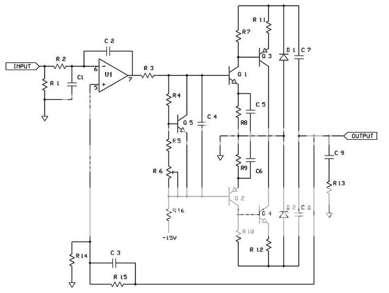
I cant see how this circuit could possibly work with the output grounded and the centertap of the filter caps made the output.
this is answered quite easily:
instead of fixed supply voltages in respect to ground and a modulated output signal, with this amp the supply voltages are floating and therefore the virtual ground (center tap between filter caps) is modulated with the supply voltage.
Weird design. So if the output devices go south this circuit doesent blow the speaker since it essentially is a capacitor coupled output.
Thats about as far as i can see the advantage, after that i only see the disadvantages of capacitor coupled output, reduced low end response, lower audio quality due to lytics in the signal path and that stuff.
Thats about as far as i can see the advantage, after that i only see the disadvantages of capacitor coupled output, reduced low end response, lower audio quality due to lytics in the signal path and that stuff.
okay, great.
i want to run the amp at about 45V DC, which should be ok for the transistors.
is there any benefit of driving the opamps by a transformer winding instead of the zener diode voltage regulation? the transformer i want to use has two unused 9-0-9 windings i could use.
Weird design. So if the output devices go south this circuit doesent blow the speaker since it essentially is a capacitor coupled output.
Thats about as far as i can see the advantage, after that i only see the disadvantages of capacitor coupled output, reduced low end response, lower audio quality due to lytics in the signal path and that stuff.
If +/- 40DC then you can use TIP142/147 Darlingtons.
Better use that 9-0-9 for best performance than zener regulation.
@ Tekko, You can get DC coupling by using a center tapped trafo, in that way no more LF thru elcos.
If +/- 40DC then you can use TIP142/147 Darlingtons.
Better use that 9-0-9 for best performance than zener regulation.
ok, so i'll use the secondary winding. its only +40Vdc, as its single rail floating, in other words +/- 20Vdc in respect to ground. i want to use the parts i have at hand so i want to use 2SD2488 and 2SB1620.
ok, so i'll use the secondary winding. its only +40Vdc, as its single rail floating, in other words +/- 20Vdc in respect to ground. i want to use the parts i have at hand so i want to use 2SD2488 and 2SB1620.
One more thing missing is Common Mode Voltage divider.
Put 2 X 22k resistors in series with each end to rails and midpoint to + input of Opamp, it will balance your output stage.
One more thing missing is Common Mode Voltage divider.
Put 2 X 22k resistors in series with each end to rails and midpoint to + input of Opamp, it will balance your output stage.
its ommited in several commercial designs, so it isnt really necessary. but i'll add it, it will surely give better performance
instead of fixed supply voltages in respect to ground and a modulated output signal, with this amp the supply voltages are floating and therefore the virtual ground (center tap between filter caps) is modulated with the supply voltage.
I dont get it. The power supply rails are fixed by the zeners at +/- 15v. What do you mean virtrual ground? (like an opamp virtual grnd that has a zero voltage but dosnt sink any current?) Have you simmed this? Isnt the simmed voltage at a ground always zero?
its ommited in several commercial designs, so it isnt really necessary. but i'll add it, it will surely give better performance
Only omitted when you have centre tap transformer.
Member
Joined 2009
Paid Member
You must use a separate supply for the opamp, or connect the D6, C5 node to the D3, R17 node (and mirror for the negative rail).
The TL072 is a poor choice for this circuit, the NE5532 works much better.
Will the BD139/140 devices sustain 90V (±45V)?
Don't forget the load Zobel.
Don't forget a 470K resistor on the - input to ground (if the pot wiper 'scratches' it will slam to the rail).
You will probably need some compensation caps too.
@djk:
why is TL072 that bad? i want to use parts i have lying around and i dont have any ne5532.
the amp isnt running 90V, but 45V. Its powered by a single 32V secondary, without center tap, so bd139/140 should be fine.
how do i add a seperate low voltage supply to my design? i would leave out R17/R18 and D5/D6 and put the rectified 9-0-9 across C4/C5. will that work?
i corrected my schematic. changes:
- opamp supply wired correctly
- common mode voltage divider added
- 470k input resistor added
- zobel network added
- collector-rail resistors added
Attachments
"why is TL072 that bad? i want to use parts i have lying around and i dont have any ne5532."
It's not totally needed, but when a TL072 has its input over-driven the output will go through a phase inversion and sometimes latch to the rail. This does not sound good. A 5532 doesn't do this, and it just plain sounds better even at lower volume levels. There are probably other opamps that will work and sound well too, I just mention the old workhorse 5532 as it is common. Older J-fet input opamps like the TLxx and LFxxx series have the phase inversion problem, newer one like an AD825 don't.
"the amp isnt running 90V, but 45V. Its powered by a single 32V secondary, without center tap, so bd139/140 should be fine."
I missed that, you should be fine.
"how do i add a seperate low voltage supply to my design? i would leave out R17/R18 and D5/D6 and put the rectified 9-0-9 across C4/C5. will that work?"
Leave out R17, R18, D7, D8, R22.
I would make the transformer connection 18-0 and use two half wave rectifiers and a pair of 1000µF to get ±25V and use a pair of 330R 1/2W resistors from the raw ±25V to pins 4, 8 of your schematic. D5, D6 will regulate it down to ±15V, C4, C5 need only be 10µF or so.
You might be able to get away with 9-0-9 rectified without regulation, but be prepared to go with the regulation if needed.
- Status
- This old topic is closed. If you want to reopen this topic, contact a moderator using the "Report Post" button.
- Home
- Amplifiers
- Solid State
- Will it work? Grounded Source + Darlington