I wondered if anyone would be interested in the results I just got from measuring the distortion of one of those £25-a-pair Quad 405 clone boards 'out of the box'.
My test setup comprises a PC with M Audio Audiophile sound card feeding the amp and monitoring the output. It's my own software that runs at 16 bit resolution, 44.1 kHz - I must get it going at 2496 if possible! The amp is powered off a +/-50V supply with 10000uF across each rail.
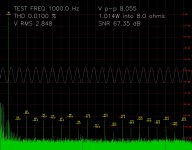
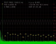
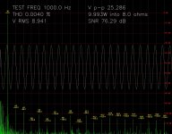
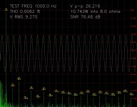
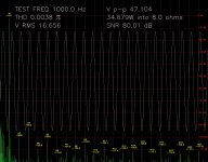
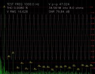
I tested the amp with a 1kHz sine wave and an 8.2R load resistor, plus a real speaker for comparison (a big rubbishy Sony thing from the '80s). I tested 1W, 10W and 35W output powers.
As far as I can tell, the amp is made to the very original 'pre-Mk1' design as shown in Peter Walker's original paper to the AES in 1975 so many, many improvements are apparently possible. Like the early reviewers, I found the noise performance to be too bad to make distortion measurements at very low powers. Apparently changing the op amp topology from inverting to non-inverting works wonders with this. Several other mods are supposed to further improve the distortion.
Nevertheless, the distortion seems very low to me...
Should this amplifier sound any good, or do those spectral lines scream that it will sound terrible?
Something that I thought might be of interest is the difference in results between the test resistor and a real speaker which shows a factor of 2 difference in distortion at high power.
Another thing I'm interested in is whether it is possible to isolate the 'residual' distortion by removing the fundamental from the complex FFT and calculating the inverse FFT. Has anyone here done this already?
(A point concerning the screenshots: there is an apparent discrepancy between the heights of the green bargraph and the indicated harmonic dBs. Although the green bargraph display shows the raw windowed FFT response, the 'H2 -98.4'' etc. indicate the relative total dB level of each harmonic, summing the power over several adjacent bins to correct for the effects of windowing.)
My test setup comprises a PC with M Audio Audiophile sound card feeding the amp and monitoring the output. It's my own software that runs at 16 bit resolution, 44.1 kHz - I must get it going at 2496 if possible! The amp is powered off a +/-50V supply with 10000uF across each rail.
I tested the amp with a 1kHz sine wave and an 8.2R load resistor, plus a real speaker for comparison (a big rubbishy Sony thing from the '80s). I tested 1W, 10W and 35W output powers.
As far as I can tell, the amp is made to the very original 'pre-Mk1' design as shown in Peter Walker's original paper to the AES in 1975 so many, many improvements are apparently possible. Like the early reviewers, I found the noise performance to be too bad to make distortion measurements at very low powers. Apparently changing the op amp topology from inverting to non-inverting works wonders with this. Several other mods are supposed to further improve the distortion.
Nevertheless, the distortion seems very low to me...
Should this amplifier sound any good, or do those spectral lines scream that it will sound terrible?
Something that I thought might be of interest is the difference in results between the test resistor and a real speaker which shows a factor of 2 difference in distortion at high power.
Another thing I'm interested in is whether it is possible to isolate the 'residual' distortion by removing the fundamental from the complex FFT and calculating the inverse FFT. Has anyone here done this already?
(A point concerning the screenshots: there is an apparent discrepancy between the heights of the green bargraph and the indicated harmonic dBs. Although the green bargraph display shows the raw windowed FFT response, the 'H2 -98.4'' etc. indicate the relative total dB level of each harmonic, summing the power over several adjacent bins to correct for the effects of windowing.)
Attachments
-
 screengrab_1kHz_1W_8R_res.jpg138.5 KB · Views: 2,747
 -
 screengrab_1kHz_1W_8R_spk.jpg138 KB · Views: 2,605
 -
 screengrab_1kHz_10W_8R_res.jpg150.7 KB · Views: 2,519
 -
 screengrab_1kHz_10W_8R_spk.jpg150.5 KB · Views: 2,482
 -
 screengrab_1kHz_34W_8R_res.jpg162.1 KB · Views: 2,452
 -
 screengrab_1kHz_34W_8R_spk.jpg168.7 KB · Views: 530
Looks like a run of the mill semiconductor amp distortion signature to me. All the "grass" is either the noise floor of your measurement setup or caused by supply ripple in the amp. Noise would be uniformly distributed. Ripple would show up at multiples of 50/60 Hz and IM products caused by the ripple would show up at multiples of 50/60 Hz of the input signal frequency and its harmonics.
~Tom
~Tom
Tom, thanks. Yes there's definitely some mains stuff at the bottom end.
This current dumping amplifier is noted for its noisiness in general in its un-modified form, but is supposedly good for its low distortion, which can be nulled out further if care is taken with component selection and other potential mods.
If the distortion figures I've shown are just run-of-the-mill I think I may just give up and buy a cheap Japanese amp on eBay!
(of course I won't)
How do you calibrate the THD of the sound card? Did you subtract the soundcard distortion from the amp output (multiplied by the gain of the amp)? Also how did you calculate SNR I don't see any noise above -93 dB or is it SINAD
Also as Tom mentioned the noise looks like power related, you cannot blame the amp for a noisy power supply, I would nullify the power hum related components as well.
Also as Tom mentioned the noise looks like power related, you cannot blame the amp for a noisy power supply, I would nullify the power hum related components as well.
Last edited:
Hi Nico
Almost certainly there will be some hum loop-related noise in the system. I may temporarily remove the amp's earth to see what it does. However, I can tell you that the amp is noisy when idling. One early reviewer (of a real Quad 405) put it very diplomatically: "Generally it is felt that the noise performance meets realistic requirements", but also rated it as one of the best amps he had tested.
As regards the software, I didn't try to compensate the sound card's own noise and distortion - it is a very good sound card - as I thought that the exact method of doing that might prove controversial. The noise and distortion figures are therefore most likely better than the ones I'm displaying.
Now you may know more about this stuff than me: I fed the sound card's output to the amp via a pot and fed the amp's output back into the sound card via a fixed resistive attenuator (so at the low power tests I wasn't using the sound card's dynamic range very well but I figured the amp was so much noisier than the card it didn't make much difference). I calibrated the displayed Vp-p and VRMS (and therefore power into 8R) readings against an oscilloscope although I might have been able to do that by calculation if I had looked up the sound card's specs.
The spectral display amplitudes and dB readings are referenced to the summed total FFT power where 'power' is defined as FFT bin magnitude squared (and 'magnitude' is defined as sqrt (re*re+im*im)). Each FFT bin amplitude is displayed as 10*log10(bin_power/total_power).
Without referring to the code, from memory THD is 100*sqrt (harmonics_power)/sqrt (fundamental power) and SNR is calculated as the 10*log10((fundamental_power + harmonics_power)/(total_power-harmonics_power-fundamental_power)). No individual noise frequency bin goes above, say, -93 dB, but the sum of all their powers brings the total noise level up to -70 dB or whatever is displayed. Does that sound about right to you?
I just found out something quite significant, I think. The 405 clone boards faithfully reproduce the well-known error on the original 405-1 schematics and PCBs: the output Zobel network is grounded to the input signal ground (which is isolated from the power ground by a 10R resistor), not the power ground as it should be, explaining why I experienced catastrophic oscillation which destroyed a tweeter the first time I plugged one of these things in without anything connected to the signal input ground. It happened again tonight when I powered up the second channel without any signal connected - luckily it was driving a test resistor at the time.
Unfortunately it will be a day or two until I can repeat the distortion tests.
Unfortunately it will be a day or two until I can repeat the distortion tests.
With the Zobel networks connected to the correct ground, the amps no longer destroy tweeters, and distortion measures just slightly better at high powers.
Tested with a Mordaunt Short MS320 bookshelf speaker as load - working towards plugging in the good speakers! Must be an easier load than the 80s Sonys. THD now 0.004% at 1kHz 40W RMS, and I'm not taking the sound card's distortion into account. Is this a run-of-the-mill figure, or quite good? (I'm pretty sure my software's right).
...
Finally plucked up the courage to power both amps into the good speakers. Sounds bloody good, if you ask me.
About 30 years ago a friend and I built some Quad 405 clones. As we did not have suitable test equipment to measure the distortion we modified one amplifier to a non-inverting configuration and used it to provide the gain in a passive LC oscillator, the distortion level measured at 0.0018% which at the time was very good.
Stuart
Stuart
Hi Stuart
I am going to try and improve my measurement method, including cancelling out the sound card's own contribution to the distortion.
Judging by your moniker, you are a 405 devotee. Why do you think the current dumping method hasn't taken over the world, particularly in DIY, and people still mess about with preset pots and thermal drift etc.? One factor, I imagine, is that the Quad implementation uses an op amp, and this is considered a 'no no' in audio circles. The cheap Chinese clones I bought are to the original MkI design, so the op amp is an LM301! But switch them on and beautiful music pours forth.
I've changed my mind about the noise performance. It's not an issue in reality. Just a slight hiss from the tweeter if you put your ear right next to it. No audible hum at all.
The topic of the 405 comes around from time to time. Are you aware of Bernd Ludwigs mods here?
http://www.keith-snook.info/QUAD/QUAD-405-Modification/405_Qw_7.pdf
The later Quad current dumpers seem to have quite different circuitry to the 405 but whether the topology is the same or not as the 405 I am not sure.
As to why they have not taken over the world I think it would be patent issues initially. And now people have forgotten the technique plus a marginal cost increase from a bog standard design.
Hi Firestorm
To be honest, I haven't tried my software with anything other than an op amp-based headphone amplifier which gave very low THD. However, I did try the sound card with a direct loop back and found that its own distortion and noise are not quite as negligible as I thought.
My next steps are to make the input attenuator variable (it's silly that I'm not driving the input to full scale all the time) but with sufficient impedance to prevent blowing the input up accidentally, and to characterise the system's inherent noise and distortion to compensate for them. I figure that I will have to normalise the harmonics in the FFT to the phase of the fundamental so that I can then subtract the sound card's THD in the complex domain. (Conceivably, distortion in the sound card could actually be reducing the measured THD of the amp, by compensating for a 'wiggle' caused by the amp in the opposite direction. Unlikely, but possible.)
I will assume that noise in each frequency bin sums with the power of the magnitudes, and that if I average enough FFTs together over time I can simply subtract the power of the sound card's noise. Or something like that! I also think I may be contributing noise/distortion to my generated sine wave with rounding errors, so I will look at tweaking that.
One thing I have realised about such a sensitive system is its usefulness in neutralising imaginary worries such as whether the two amplifier channels are matched or one is damaged, or whether a component change or a change in grounding has been beneficial or detrimental. For example, I am planning to fit a triac-based crowbar circuit across each amplifier output, and without this software I might have imagined that it was, in some way, contributing distortion or shaving a bit off the top end. I will be able to check in real time whether there is any effect whatsoever if I touch the wire on and off.
As regards the sound of the unmodified 405 clone to my ears it sounds excellent. There's only a slight 'thump' at start up, and it seems well-behaved at power down. (I found that changing the op amp to a TL071 or OPA134 without any other changes led to a slight squeal when powering down with the source still playing when I tried it, but that was before I corrected the Zobel error on the PCB.)
My one concern is the notorious SOA limiting of the Mk I 405 and whether it is cutting in at high listening levels on my 'good' speakers, which are nominally 6 ohm impedance but which may drop under certain circumstances (who knows?). I would like to either remove those components (dangerous?) or replace them with the Mk II limiters (a bodge). Obviously I'm not too worried about blowing up the amps themselves (£25 a pair inc. P&P) but I am worried about my speakers. Hence the desire to fit crowbar circuits like Quad fitted themselves. I can't think how to guard against HF oscillation blowing up the tweeters except with an active circuit which shorts across the output with a relay when it detects it. I would like to avoid relay contacts in series with the signal path if possible.
Or do I go the whole hog and design fresh PCBs to the Mk II circuit, including the crowbars? I am convinced that the Quad current dumping design is the way of the future and I can't imagine bothering with those other primitive topologies from now on!
Consort-ee-um
Thanks, yes, I've been looking at some of the many 405 mods around the interweb. Some of them seem quite significant like changing the op amp stage from inverting to non-inverting which reputedly improves noise and distortion quite a lot. Whether or not I like the idea of changing Quad's basic design I'm not sure - even if Quad did drop quite a howler (literally) with their Zobel grounding error in the original design. Quite how they missed that one is beyond me.
Thanks, yes, I've been looking at some of the many 405 mods around the interweb. Some of them seem quite significant like changing the op amp stage from inverting to non-inverting which reputedly improves noise and distortion quite a lot. Whether or not I like the idea of changing Quad's basic design I'm not sure - even if Quad did drop quite a howler (literally) with their Zobel grounding error in the original design. Quite how they missed that one is beyond me.
Lazy?
Its a real shame that they didn't clone a Mark II or even look at all the simple mods that have been applied to these and make the PCB to suit.
Then I "might" have been interested.
The topic of the 405 comes around from time to time. Are you aware of Bernd Ludwigs mods here?
http://www.keith-snook.info/QUAD/QUAD-405-Modification/405_Qw_7.pdf
The later Quad current dumpers seem to have quite different circuitry to the 405 but whether the topology is the same or not as the 405 I am not sure.
As to why they have not taken over the world I think it would be patent issues initially. And now people have forgotten the technique plus a marginal cost increase from a bog standard design.
Its a real shame that they didn't clone a Mark II or even look at all the simple mods that have been applied to these and make the PCB to suit.
Then I "might" have been interested.
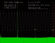
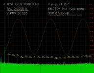
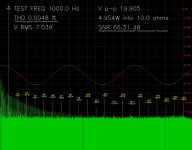
I got my software and M-Audio Audiophile card working in 24 bit. I enclose the result of a loopback test (phono cable between output and input - ignore the displayed power value). I found that I got a significantly lower distortion value by running the system at 50% full scale amplitude, which tallies with something I read somewhere.
So the intrinsic THD at 1kHz is 0.0005% and at 7KHz 0.0011% (first three harmonics only I'm afraid).
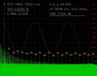
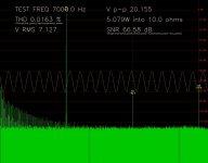
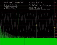
I then re-measured the 405 clone's distortion at 1kHz & 7kHz, at 5W & 50W into a 10R dummy load without attempting to null out any of the intrinsic distortion.
1 kHz:
5W 0.0048%
50W 0.0026%
7 kHz:
5W 0.0163%
50W 0.0101%
Is this in any way similar to a 'real' 405?
So the intrinsic THD at 1kHz is 0.0005% and at 7KHz 0.0011% (first three harmonics only I'm afraid).
I then re-measured the 405 clone's distortion at 1kHz & 7kHz, at 5W & 50W into a 10R dummy load without attempting to null out any of the intrinsic distortion.
1 kHz:
5W 0.0048%
50W 0.0026%
7 kHz:
5W 0.0163%
50W 0.0101%
Is this in any way similar to a 'real' 405?
Attachments
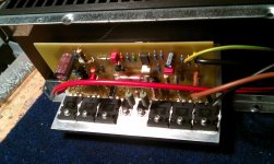
Hi. Does anyone know how to connect the fifth luger-style connector which is labelled "gnd". Looking at the board i see the two phono input terminals then speaker out then the two 54 volt outputs then there is a gnd connector which my original quad boards do not have. I connected this back to the smoothing capacitors of the power supply via the green wire but just get massive distortion.
Many thanks in advance. John.
Many thanks in advance. John.
Hi Stuart
Why do you think the current dumping method hasn't taken over the world, particularly in DIY, and people still mess about with preset pots and thermal drift etc.? One factor, I imagine, is that the Quad implementation uses an op amp, and this is considered a 'no no' in audio circles.
Hi
Mainly marketing problems. Quad 405 has no sophisticated gimmicks inside. And only a few people realised the beauty of its design.
There are some newer versions without op amp in the signal path. (Imagine how many op amps are in the signal path before the audio conserve (CD, LP) arrives to the listener. And there are some newer designs using the same forward error correction topology (by diyaudio members like boraomega or tvicol).
In eastern Europe the Quad 405 was very populay among diyers as it gives good results with the modest components available there once.
Hello Coppertop,
I am also experimenting with QUAD 405 Cheap Clones from China - which are using the KTD1047 Power Transistor. I have 3 Boards, each giving different distortion numbers using RightMark Audio Analyzer (6.2.3) , specifically under Load (4 Ohm Resistor) the distortion is 'jumping' high. I am impressed by your own measurment SW. Is there a chance that I may use your SW to post my measurements for comparing with your results ?
Rgds,
Thomas
i'm very interested in results
i gonna make a monster
and 80's technics su-v50 with not longer avaliable burned amp ic svi4004
i will put inside a pair of 25 euro 405 clone pcb's
i was looking the desing, and is exactly the same of circuit 12333 issue 5, the last 405 mk1 mounted in a M12368 9 and 10 bassed pcb
the technics transformer seems to be enough big, the power consumption is 490W
i think it have avaliable 300VA to drive 2 pcb's
output voltaje in 405 power supply is +-50, in technics +-48
i know where pream lines are, i will put a relay speaker protector and a new recicled big sink
i'll let you know the results
cheers
- Status
- This old topic is closed. If you want to reopen this topic, contact a moderator using the "Report Post" button.
- Home
- Amplifiers
- Solid State
- Cheap eBay Quad 405 Clone measurements