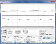
Here it is:
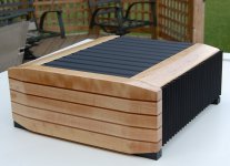
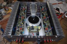
6 channels of my Patchwork amps. This is used exclusively to actively drive my main speakers - 3-ways. It has been in daily use since I finished it.
Though I am perfectly happy with its performance, I want to improve the power supply. Mainly, this is just whimsy - the existing power supply is more than adequate but I can't leave well enough alone.
The Plan:
I will change the main power transformer from the current 700VA, 40-0-40 toroid to a ~600VA EI 46-0-46. I may (depending on space within the existing chassis) regulate this supply. This will supply the output stages of the amp modules.
I will add two 12VA 48-0 transformers to create a highly filtered and regulated supply for the front end of each amp module.
At this time, I'm not sure how I want to filter the front end supply. Cap multiplier or passively, CLC perhaps.
Create a new softstart circuit. I already have a softstart in the amp, but I can improve upon the original design.
Thoughts, comments, concerns welcome.
🙂
Member
Joined 2009
Paid Member
If it means messing up that gorgeous chasis - don't do it !
On the other hand, if it means you'll have a redundant 700VA 40-0-40 you can send to me, go for it 😀
I like the split supply for front-end and back-end. I've no experience with cap mux but a CLC has little to go wrong, using a common mode choke for the L to keep size and cost down.
On the other hand, if it means you'll have a redundant 700VA 40-0-40 you can send to me, go for it 😀
I like the split supply for front-end and back-end. I've no experience with cap mux but a CLC has little to go wrong, using a common mode choke for the L to keep size and cost down.
On the other hand, if it means you'll have a redundant 700VA 40-0-40 you can send to me, go for it 😀
.
I won't be doing anything with the outside of the chassis and I'm afraid I'll need to re-purpose that transformer Gareth...next amp project needs it. 😀
This is the preliminary stage - the planning stage. I'm not actually going to do much yet but I would like some input.
The amp as it is today:
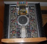
needs a dusting! (one of the reasons for upgrading it - to clean it! 🙂 ).
Member
Joined 2009
Paid Member
Playing it safe is no fun Gareth. 🙂
I have had THIS project on my schedule for quite a while now and it's nearly time to start. I just have to finish up another mega-project first - This One.
I have simulations to run, transformers to test.
One question for anyone out there that might know: is there any problem completely enclosing an EI transformer? I would like to make a steel box that covers it. I thought I read somewhere that this can be a problem.
I ran a series of load tests on the proposed new power transformer for the output stages. I initially estimated the transformer to be in the 600VA range and it looks like I'm off by a bit.
The series output voltage with no load is 93VAC. I worked my way down to 13.7ohms of nichrome wire and I have 86VAC at that load. That is 6.28A at less than 10% regulation - not bad and should be suitable for this part of the project.
The series output voltage with no load is 93VAC. I worked my way down to 13.7ohms of nichrome wire and I have 86VAC at that load. That is 6.28A at less than 10% regulation - not bad and should be suitable for this part of the project.
Member
Joined 2009
Paid Member
I liked your original amp a lot.
Shame to muck about with it.
I loved the aesthetics.
What about two 3channel versions? The extra space would allow the room for the HV transformer and the HV PSU.
I am not keen on replacing a 8.75Aac low regulation transformer with a 6.28Aac higher regulation transformer.
BTW,
How do you check that your 13r7 nichrome wire is still 13r7 when passing 6.28Aac?
I loved the aesthetics.
Thanks Andrew,
The outer appearance will remain unchanged, just guts will get 'improved'.
What about two 3channel versions? The extra space would allow the room for the HV transformer and the HV PSU.
I need 6 additional channels in my next project (centre channel - 2, rear surrounds - 2 each) and if it were possible, I'd put those in that case too! I'd really like to reduce the quantity of individual components.
I am not keen on replacing a 8.75Aac low regulation transformer with a 6.28Aac higher regulation transformer.
BTW,
How do you check that your 13r7 nichrome wire is still 13r7 when passing 6.28Aac?
Regarding the transformer, I ran one more load test last night - 10 ohm load and the voltage dropped to 83.4. Allowing for a rise in resistance with temp, say a worst case 1000*C rise will increase resistance to ~11.4 ohms. That gives me 7.3A at ~10% regulation and I believe this is more than adequate for this application.
TBH, I don't think the transformer that is in place now has seen anywheres near it's potential, as for actual loading. Over-speced, current wise but not having a high enough voltage (and its size) is the reason I want to pull it.
the voltage dropped to 83.4. Allowing for a rise in resistance with temp, say a worst case 1000*C rise will increase resistance to ~11.4 ohms. That gives me 7.3A at ~10% regulation
Your measurements are showing 11.5% regulation at 600VA (7.3Aac).
I would expect the toroid to be <4% at 700VA (8.75Aac).
I still don't like it. I think you are going to see 4times as much voltage variation coming from the EI transformer vs the toroid transformer.
I think the advantages outweigh the one (questionable) drawback. Advantages: physically smaller unit (very important), higher voltage (very important). Losing a bit of current capability will not be detrimental, I think. After all, I'm not halving the VA rating.
What I have in mind for the front end supply:
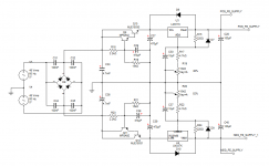
Extremely low ripple. Regulated to +/-56VDC.
The cap multi / linear regular combo seems to be the most cost/space/results efficient method.
What I have in mind for the front end supply:

Extremely low ripple. Regulated to +/-56VDC.
The cap multi / linear regular combo seems to be the most cost/space/results efficient method.
post11.
Add pads for a series resistors with C32,31 etc.
Allow a larger cap value for C30. upto 220uF
Replace D6 with a 30 to 36V Zener. To limit start up Vdrop across the regulator.
Consider replacing R17 with a high value Zener.
Carefully consider where C33 and C37 connect to PSU ground. You don't want charging pulses getting in to the route from PSU output 0volts to the junction of R19+C30
Great tips Andrew!
New scheme:
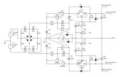
A marked decrease in output ripple (mainly due to the 220uF caps at the adjust pins of the regulators).
Added a disconnect to split the ground. Yet to be determined if the best place to ground the cap multi is before or after the disconnect. Hard to determine the appropriate values for snubber resistors R24, R25, R28, R29 as I don't know the frequency to target. Is there a chance of seeing this on my 400Mhz scope?
New scheme:

A marked decrease in output ripple (mainly due to the 220uF caps at the adjust pins of the regulators).
Added a disconnect to split the ground. Yet to be determined if the best place to ground the cap multi is before or after the disconnect. Hard to determine the appropriate values for snubber resistors R24, R25, R28, R29 as I don't know the frequency to target. Is there a chance of seeing this on my 400Mhz scope?
Last edited:
you don't have to fit r24 or make c30 that big, but the PCB is laid out to allow flexibility.
400MHz is way more than enough to see PSU/rectifier ripple. mVac might be the bigger problem.
You may have to artificially stimulate it with fastish current pulses to see the evidence.
I doubt the addition of the disconnecting network is necessary, but you have the right idea.
Think where the charging currents and pulse currents are going and ensuring the voltage monitoring currents are not contaminated.
There was a paper done decades ago and occasionally it is linked in this Forum. I can't remember the author.
Last edited:
you don't have to fit r24 or make c30 that big, but the PCB is laid out to allow flexibility.
I doubt the addition of the disconnecting network is necessary, but you have the right idea.
Think where the charging currents and pulse currents are going and ensuring the voltage monitoring currents are not contaminated.
There was a paper done decades ago and occasionally it is linked in this Forum. I can't remember the author.
I will attempt to see if I can determine the snubber frequency but I probably won't lose sleep over it. If I can , I'll install the Rs, otherwise, I'll jumper the pads.
I have had nothing but excellent results whenever I use a disconnect, as long as it is in the correct place. I will try it with and without, grounding the cap multi before and after to get the best results.
A look at the main supply:
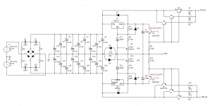
42,000uF capacitance per rail (this is actually one 4700uF cap less than the 'old' supply), regulated output. The base drive for the driver transistors Q3 and Q5 comes from the front end supply rails - very clean.
This is what I want, but it may not fit, especially if I need more than 3 pass devices per rail.
Hi,
are you aware of Hagerman? His paper on snubbers is very thorough.
ps. I am so glad you posted the simple layout first !
are you aware of Hagerman? His paper on snubbers is very thorough.
ps. I am so glad you posted the simple layout first !
Hi,
are you aware of Hagerman? His paper on snubbers is very thorough.
Tricky measuring the inductance of the secondary without an inductance meter. Any tips?
ps. I am so glad you posted the simple layout first !
Nothing tough under the sun for you, my friend! 😉
Last edited:
there's a Member on the Forum that posts simple techniques for determining transformer parameters and fault finding with few resources.Tricky measuring the inductance of the secondary without an inductance meter. Any tips?
Can someone give MJL a name to search?
I suggested he write up a paper for a future Wiki but he seems to prefer answering specific questions.
Main power supply concerns.
I have determined that I have enough room in the case for the full regulated supply, but...
If I regulate, how much heat will the regulator have to dissipate? Looking at the existing 6 channels, they each have 4 output devices, each are biased to ~70mA, giving a total idle dissipation of 1.7A, or about 94 watts. The regulator itself will only dissipate the power it drops, or about 2.5 watts per device (assuming 3 pass devices per rail).
At a heavier load, say 5A per rail, that is only ~13 watts dissipated in each pass transistor - total = less than 80 watts.
So, my idea is to use a piece of thin heatsink, 6" wide, 17" long and a bit more than 1/2" thick. This will cover the centre space of the chassis, with the amp modules on either side. The fins would face up and the regulator PCB would be underneath. Heat from this sink will escape through the spaces between the slats of the top.
Before I commit to this, I will test it.
- Status
- Not open for further replies.
- Home
- Amplifiers
- Solid State
- Patchwork 6: Power Supply Upgrade

