What gives? Everyone here works really hard on their power supplies but I did a search and found almost nothing on power regeneration. Has anyone built a 60 Hz power regenerator, or a simple clone of a PS Audio Powerplant? (http://www.psaudio.com/products/p300.asp)
I am thinking about this, it should be easy to make a clean sine wave (well, cleaner than the wall outlet sine wave), amplify it, and step it up (via transformer). You could even get balanced power on the output if you wired in the right type of step-up transformer.
Or else, you could just rectify your amplified sine wave and get DC out of it, and feed the DC to your preamp or other DIY circuit.
Anyway, just wanted to see what the feeling was here on power regeneration.
I once started a thread on a subject. Ended up buying UPSfor $30")
http://www.diyaudio.com/forums/showthread.php?s=&threadid=3674&highlight=power+regeneration+anybody
http://www.diyaudio.com/forums/showthread.php?s=&threadid=3674&highlight=power+regeneration+anybody
diy powerplant
Yes I had a go....
It's a lot less straightforward than you might expect. The oscillator section is comparatively simple - a good Wien bridge design will give you distortion down around the 0.01-0.02% mark - if you are careful. The problems come with everything after that stage: output impedance affecting regulation and noise/distortion performance; efficiency (lack of it); and what happens when you connect a 'real world' load.
I was sufficently intrigued by the possibilities to try building such a unit out of the 'bits box' about 18 months ago and this is what I found:
1) The oscillator drifts slightly in frequency, but that's no problem, we only want low noise and harmonic output. More seriously the oscillator drifts in amplitude - and this is amplified by maybe 10-20x by the power amp and step-up stage.. a much bigger problem, constant voltage is a design requirement; it is no good having 240v output, -/+30v depending on temperature and the weather outside. One potential fix: use a lookup table and a DAC. You need to be familiar with PICs (complexity) and you *really* need to know what you are doing to better the distortion performance of even a simple Wien Bridge oscillator.
2) Next problem: power amp. Chip amps are worth a try for experimental purposes (low cost) but this beast is going to run 24/7 with some expensive electronics depending on the output. Whatever your solution, make sure the power supply, heatsinking and parts choice is up to it, and that the unit will shut down gracefully in a fault condition. You'll waste a lot of heat - and therefore money- here. The power amp needs very good distortion performance, low output impedance maintained to high frequency (>>50Khz). It must also be unconditionally stable i.e. immune to noise injection at the output, and designed to run at maximum output even into an inductive load (if your load is ever becomes disconnected, or you turn it off).
3) Linking the power amp output to the load is most critical, and dominates performance. Unless you are a genius, rich, or a combination of both, the amplifier will be feeding the output via a step-up transformer. A *good* one, or hysteresis and limited HF performance will destroy your low distortion perfomance. This transformer must have good regulation i.e. low impedance - you need a big, good quality piece of iron much larger capacity in fact than the load it is to carry. The 'rich//genius' solution would be to drive the output direct using high voltage poweramps ( valves maybe?). Even the PS Powerplants for Euro voltages are only the US version with a step-up transformer... The other, unseen problem is that the step-up ratio increases the output impedance of the whole supply eg if your power amp stage has an output impedance of 0.1ohm at 50Hz and swings 24v RMS then the best output it will manage supplying another piece of equipment is 1ohm output impedance at 50Hz, because you need 10: 1 voltage step up. If your output transformer is less than grossly oversized, its own regulation problems will magnify this effect. Equally, any noise reflected from the load will appear directly across the transformer output unless it is also an exceptionally wide bandwith device which can transfer the noise to the power amplifer _and_ the power amp has a sufficiently low output impedance at high frequencies to make it all go away.
I had a lot of fun building such a device to power a source component (CD player). I wanted 15W at 240V/50Hz. The plan was to lash-up a basic oscillator + power amp + trafo together and test it to identify major problems before investing big $$$ in parts. A relatively refined Wien bridge oscillator was built for which I trimmed distortion << 0.0005% (ie beyond my ability to reliably measure with a cheapo soundcard). Hooked my big 'test' PSU up to a a bridged LM1875-based power amp stage with very good heatsinking and a refined layout, driving a 50VA transformer step up to get 240V out. This I tested with a desktop halogen light (transformer type, not electronic ballast) and actually measured, at the output, <0.04% THD+N while driving 20W into the load. Pretty good, I thought, given the chip poweramp: >0.38% of the 'extra' distortion was entirely due to hysteresis effects in the step-up transformer. I did try a monster trafo, but the difference was not significant. My local mains supply averages 4.5% THD, so the DIY approach represented about 20dB improvement. I could vary the oscillator 40-280Hz, and got better efficiency at higher frequencies as well as slightly lower distortion. Then I connected a 'normal' load, one which contains a transformer and rectifier bridge.
And it all looked horrible, no matter what I did.
The reason is simple: rectifiers, even on the otherside of a transformer, are horrible, non-linear loads,and the output impedance of a DIY regenerator is just too high to deal with it - the result is massive THD and noise issues. Much worse waveform, measured anywhere in the load side, than just plugging into the mains. Oh, and balanced output makes no difference if the waveform is basically S**t!. The difference is so great that I would *really* like to measure what happens at the output of PS-Audio unit when it's running a load like an amplifier. Also, the whole unit consumed around 48W just to supply 17-18W at the output...not very good if that scales up also!
At home, my mains power sockets have an output impedance <<0.1ohm (easily demonstrated with a 3KW kettle and a voltmeter) and cost nothing to run when I don't use them. I gave up on the DIY regenerator as a serious alternative....but if you want to experiment, don't let my experience stop you!
Hope this is of interest -
Martin
I made.
I used WIEN bridged RC oscillator to get low distorted 50Hz. I use opamp for the precise adjustment for the output level.
The output of the oscillator drive the push-pull MOSFET power amplifier, which get the 320V DC from the rectified mains.
I used output transformer, with separeted feedback windings, to keep the output free from the mains.
The distortion was less than 0.2% with 500W resistive load, the maximum output was approx. 700W. Unfortunately I don't apply any protection, so after some miscabling my converter died
I didn't repair it (yet).
Sajti
Amusingly i followed almost exactly the steps described by Martin.
1) I did an AVR-DAC_lopass thing which synthesised a very passable 50Hz out of a 100 point lookup table. Not sure now, but definitely bellow 0.1% thd. The microcontroller route is good as it allows the generation of all sorts of 'multiwaves'
2) Used parallel 3886s which is probably a good DIY solution that scales fine if you also bridge it.
3)The big issue indeed. It seems like a low step-up is very desirable, thus the bridged, possibly high voltage amp. I guess a chip-amp with a discrete power booster to raise the supply rails and a bridge will suffice for 110v and would work with a 1:2 step-up for 220.
This i really don't understand. Martin?
4)The original purpose of this project was to feed a Garrard 301 which was quite satisfactory but didn't sound all that good feeding a cd player - a pale and thin sound. Not so much surprise here if mains cables can dramatically alter the sound...
cheers
peter
1) I did an AVR-DAC_lopass thing which synthesised a very passable 50Hz out of a 100 point lookup table. Not sure now, but definitely bellow 0.1% thd. The microcontroller route is good as it allows the generation of all sorts of 'multiwaves'
2) Used parallel 3886s which is probably a good DIY solution that scales fine if you also bridge it.
3)The big issue indeed. It seems like a low step-up is very desirable, thus the bridged, possibly high voltage amp. I guess a chip-amp with a discrete power booster to raise the supply rails and a bridge will suffice for 110v and would work with a 1:2 step-up for 220.
limited HF performance will destroy your low distortion perfomance
This i really don't understand. Martin?
4)The original purpose of this project was to feed a Garrard 301 which was quite satisfactory but didn't sound all that good feeding a cd player - a pale and thin sound. Not so much surprise here if mains cables can dramatically alter the sound...
cheers
peter
HF performance vs. low distortion: what I mean is that the transformer works both ways: so noise generated by the devices you are powering (cd player, in my example) passes through teh transformer and is reflected at teh poweramp output.
The transformer needs good HF performance, because otherwise this coupling is very poor: instead of the low output impedance of the amplifier killing the noise (noise current through low impedance = low noise voltage) the noise is reflected from the high HF impedance of the transformer back into the CD player. The result is that the power supply to the component contains more rubbish than if you had simply plugged it into the mains!
Martin.
Knew it
Great, I knew this had to have been tried before.
I guess you would need some type of automatic gain control to keep your sine wave amplitude constant. Also, if the amplifier part is not fully rectified, you will have drops in output voltage depending on the power requirement of the load. So it is not that simple.
Perhaps the way to go is to omit the step up transformer in the regenerator, and the step-down transformer in the load, say preamp, and just directly rectify your amplified sine wave into DC. You put all the circuitry into your preamp or external power supply.
It is not that damn hard........
A stable low distortion oscillator is not that hard to build. I have built this type of power regeneration and it sounded great for powering line level devices (preamp ect) application. You can use a similar power transformer for the step up as you would use in a power amp. I have also used the output transformer from a very good 200 watt tube amp. I thought the results were well worth the effort. The distortion for my oscillator was over 80 dB down and the amplitude was much more stable than my AC line voltage at the wall. Ignore the horror story and give it a try. I would use the transformer or you have to build a very high voltage balanced amp. You also get the galvanic isolation that many use isolation transformers for.
A stable low distortion oscillator is not that hard to build. I have built this type of power regeneration and it sounded great for powering line level devices (preamp ect) application. You can use a similar power transformer for the step up as you would use in a power amp. I have also used the output transformer from a very good 200 watt tube amp. I thought the results were well worth the effort. The distortion for my oscillator was over 80 dB down and the amplitude was much more stable than my AC line voltage at the wall. Ignore the horror story and give it a try. I would use the transformer or you have to build a very high voltage balanced amp. You also get the galvanic isolation that many use isolation transformers for.
Attachments
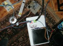
Here's UPS, I bought for $30. I'm using it as it is for line sources and it still improves the sonics (there is a difference if I run it from AC line or batteries, but usually AC is preferrable). It could probably be quite easy to convert it into true power regenerator, as the oscillator is there, so the amp and step up transformer.
Attachments
A somewhat different and (hopefully) cooler and more efficient approach is mentioned here:
http://db.audioasylum.com/scripts/t.pl?f=general&m=279286
hth, jonathan carr
http://db.audioasylum.com/scripts/t.pl?f=general&m=279286
hth, jonathan carr
What's UPS doc
"It could be probably quite easy to modify it into true power regenerator"
Tell us how then........
The fews UPS I have played with sounded pretty bad. I think it might be a total waste of time to modify one. The money would really be better be spent on a decent power transformer and a DIY amp and oscillator. This is really a pretty simple project I have seen plently of one op amp oscillator circuits around that you can probably build with Radio Shack parts. Do not use a funstion generator IC they have an incredible amount of distortion. it is not that hard to build an analog circuit to very the shape of the waveform to lengthen the diode conduction time either. I guess it is time for some people to do some actual R and D.........
Re: What's UPS doc
When was a last time you did some actual R&D, if you insist on mentioning it so often?
Fred Dieckmann said:I guess it is time for some people to do some actual R and D.........
When was a last time you did some actual R&D, if you insist on mentioning it so often?
WISDOM SHOULD COME WITH AGE...
Hi,
"A person with a deluded view of life is like a dog chasing his own tail. He believes that it is another dog’s tail. He chases the other dog around and around a tree thinking only, 'Just let me get that dirty dog!' He will never catch his own tail, just as neither wealth, power, success, nor prestige will guarantee our security. Eventually the dog dies, as do we. At that moment the dog dies, he does not know what he was about or why he dies. He is unaware that he has been chasing his own tail. Such is the deluded view of life, and many, many of us live this way."--Master Sheng-yen.
Time for some soul searching, perhaps?
Cheers,
Hi,
I guess it is time for some people to do some actual R and D.........
"A person with a deluded view of life is like a dog chasing his own tail. He believes that it is another dog’s tail. He chases the other dog around and around a tree thinking only, 'Just let me get that dirty dog!' He will never catch his own tail, just as neither wealth, power, success, nor prestige will guarantee our security. Eventually the dog dies, as do we. At that moment the dog dies, he does not know what he was about or why he dies. He is unaware that he has been chasing his own tail. Such is the deluded view of life, and many, many of us live this way."--Master Sheng-yen.
Time for some soul searching, perhaps?
Cheers,
"A person with a deluded view of life is like a dog chasing his own tail. He believes that it is another dog’s tail. He chases the other dog around and around a tree thinking only, 'Just let me get that dirty dog!' He will never catch his own tail, just as neither wealth, power, success, nor prestige will guarantee our security. Eventually the dog dies, as do we. At that moment the dog dies, he does not know what he was about or why he dies. He is unaware that he has been chasing his own tail. Such is the deluded view of life, and many, many of us live this way."--Master Sheng-yen.
amen...
Fred Dieckmann said:Tell us how then........
I guess it is time for some people to do some actual R and D.........
I'm afraid Fred's becoming another millwood
Modified sine wave
If you guys don’t mind, I’ve a few things to say about UPS's that may be mildly related to audio.
Most affordable UPS systems have inverter outputs specified as a modified sine wave. Most of us would call this modified wave form a square wave, saw tooth or ramp wave. Butt loads of harmonics. You need to spend some serious cabbage to get something like a best or Leibert UPS that has a low distortion sine wave output.
I think similar things can be inferred about the quality of the filtering and line conditioning of cheap vs. quality UPS.
These cheap things work well for our PC's because the PC's have switching power supplies that don’t care too much about sine wave distortion.
Attachments
Re: Modified sine wave
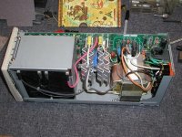
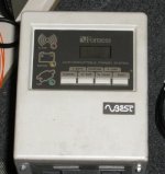
Actually my UPS is a Best and when I looked inside it's indeed some serious stuff. That's why I didn't want to touch anything, it just seems too complicated.
I wouldn't be using it, if it didn't improve the sound. Works very good with my DAC, I didn't notice much improvement with a transport and I didn't like it with Zen or GC amps.
Da5id4Vz said:You need to spend some serious cabbage to get something like a best or Leibert UPS that has a low distortion sine wave output.
Actually my UPS is a Best and when I looked inside it's indeed some serious stuff. That's why I didn't want to touch anything, it just seems too complicated.
I wouldn't be using it, if it didn't improve the sound. Works very good with my DAC, I didn't notice much improvement with a transport and I didn't like it with Zen or GC amps.
Attachments
Peter
You may be absolutely right that your ups improves the sound, but admit it: it's a dead end.
For anyone willing to experiment, a good start is a Wien-bridge oscillator as found in Art of Electronics or any other basic electronics text. Choose the circuit with a miniature lamp as amplitude stabilising element - it's usually better than the ones with fets. Use a decent opamp (5534 is perfect) and when setting the output amplitude check the distortion with one of the many freely-downloadable spectrum analysers and your computer sound card. The only real problem the Wien bridge has is the difficulty of varying the frequency - that's what prompted me to choose the AVR.
cheers
peter
- Status
- This old topic is closed. If you want to reopen this topic, contact a moderator using the "Report Post" button.
- Home
- Amplifiers
- Solid State
- Anyone Build a Power Regenerator?