Hi guys,
Am rebuilding an amp which was originally full complementary.Am through with a pair of 2sa1943/2sc5200 with a supply of +/-50v.I intend to use the amp on a 4 ohm load so i needed to add another pair to the output stage.The (only)seller tells me that she wouldn't be stocking any of that stuff in small silicon packs this coming year.She has run out of genuine 2sa1943's,just the 5200's.Am on student budget and can't buy them online(who knows?they might as well be fake!).I have a crazy idea about my situation:i did something that none of you would do.I 'fixed' the trannys onto the heatsink with epoxy since i couldn't get thermal grease.Am not about to hammer a 1943 out so i was thinking maybe i could have the first pair in full complementary and the second pair in quasi complementary...like in ampslab's c200.1 quasi complementary.What do you think?Am just doing this out of necessity and don't know if it can work,can it?
If not,what changes do i need to make on the circuit to make it a quasi complementary amp?
Regards.
Whats up with the red arrows?
That what you have to change/add , if you started out with a standard EF2 ... you didn't specify your original design.

#1 - this is just audio , we aren't transmitting AM band .. #2 -I don't use thoseHave you checked the power bandwidth? 2N3773s are mud slow transistors.
Just an example  #3 - ya mean a builder would have to wait till the new year to hear the first note out of his new amp??
OS
The original design look exactly like attachment 1 with a 220 ohm resistor in place of the 100 ohm R89.
How will it affect the performance if i solder the drivers' emitters resistors to the feedback instead of the original 220ohm resistor across the emitters?
Well , the drivers won't be running class A like a EF2 does. Performance should be on par with a fully complimentary OPS. For a closer match in operating point (voltages), 3- 56-68R resistors(instead of the 39R's) would be a close match for your present 220R Re driver stage. This means your Vbe (Bias adjust) would still be in the proper range. Start with just 1 pair outputs to perfect the "swap".
OS
Thanks Ostripper.
I hope you understand this idea i have and please let me know if it can work.
I'll use attachment 2 as an example. The first pair being full complementary,the base of the 1943 is soldered to the emittes of the driver(15031).The second pair being quasi complementary,the base of the 5200 is soldered to the collector of the driver.
What do you think? Can it work without a significant rise in distortion?
Regards.
Thanks Ostripper.
I hope you understand this idea i have and please let me know if it can work.
I'll use attachment 2 as an example. The first pair being full complementary,the base of the 1943 is soldered to the emittes of the driver(15031).The second pair being quasi complementary,the base of the 5200 is soldered to the collector of the driver.
What do you think? Can it work without a significant rise in distortion?
Regards.
No - no , NO... don't mix the 2 topologies. Either FULL quasi or full complimentary. (All 5200's)
OS
working*!
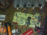
Thanks for your contribution Ostripper.I already finished the soldering.I used 68 ohm resistors excepted R20 and put a diode in parallel with a 33nf cap in place of the R.
Now its working with a supply of +/-4 volts!No distortion whatsoever before clipping.I haven't got enough guts to 'fire it up',but i will soon and post the results.
Attachments
trouble?
I used a 60W bulb,there's a slight glow when there is no load on the secondary.The glow remain the same when i connect the amp.(+/-30vdc)
Problem:there is a 30mv voltage drop across the emitter resistors when i set the pot to max.I expected the value to be almost 0mv.The good thing though is that nothing is heating up.
What do i need to do in the bias circuit to reduce the value?I read somewhere that when the amp is idling the value should be around 10-15mv.
Regards.
use a light bulb (incandescent) in series with the power xformer primary, like 25-40W.
I used a 60W bulb,there's a slight glow when there is no load on the secondary.The glow remain the same when i connect the amp.(+/-30vdc)
Problem:there is a 30mv voltage drop across the emitter resistors when i set the pot to max.I expected the value to be almost 0mv.The good thing though is that nothing is heating up.
What do i need to do in the bias circuit to reduce the value?I read somewhere that when the amp is idling the value should be around 10-15mv.
Regards.
- Status
- This old topic is closed. If you want to reopen this topic, contact a moderator using the "Report Post" button.
- Home
- Amplifiers
- Solid State
- Quasi complementary outputs in a full complementary circuit