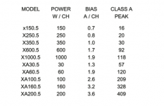
Im going to go with 70 ma's. there's a bais pot and both individual resistors on each transister of 1 ohm as well as a board resister of ten ohms. I can set the board to .7 amps, which directly translates to 70ma's on each transister. .7 is listed for a 150 watt amp. my amps is branded as a 200wpc amp. but as others have suggested, it may actually be less. it runs pretty lke warm at .6 or 60ma's so I have no issues with using .7 or 70ma's. btw, the author of the article I clip the below from, is the designer of the amp.
Attachments
a.wayne
thats funny. no some. the 1 ohm resister on each of the 24 output transisters are not even warm. the 10 ohm board resister is not even warm. heat sink is hot to hold but not to touch. It sounds better the higher I go. the adjust ments can take the board resister bias well past 1 amp. I think 1.2 amps puts it at max wall outlet draw. unless I can find something or somone that can rationalize going high than .7 board 70ma individual transister , going to go with .7.
thanks for all the assistance.
a.wayne
you know, I was coming back to post a concern. My test speakers say that they are 8 ohms, but you know how that goes. so now I need to understand, what bias should I use at 4 ohms. if the speakers really are 8 ohms, whn I go to 4 ohms, my bias will jump pretty high. According to some white papers I read, it will double. so in theory, I might be frying eggs after all.
don't know about the tranny. there is a 12amp main fuse, and a 6amp fuse for each side of the amp for each voltage phase. 4 fuses in all. A left + fuse, a left - fuse, and the same for the right, then a master 12amp fuse.
Last edited:
Hi,
the amplifier bias is not affected by the speaker impedance.
Set the bias to a value that minimises the output distortion.
Most ClassAB with EF output stage do this by biasing to a set Vre. The voltage across the emitter resistor of the output device. Usually <=26mVre.
ClassA bias for a push pull output stage is set to half the peak output ClassA current.
If you want 1Apk of ClassA current then total output bias is set to 500mA.
If you want 2.4Apk of ClassA current then total output bias is set to 1.2A.
Note changing the load impedance does not influence the bias setting.
Hi,
the amplifier bias is not affected by the speaker impedance.
.
interesting.
I got sent down this path after reading a paper by Nelson Pass about a DIY class A amp build. His check out steps goes over bias adjustments. He indicates 175ma for 8 ohms and 220ma for 4 ohms. So perhaps only in this particular project was the impedeance a factor.
I'm getting that Nelson Pass designed the Threashold line of amps, so I assumed that the basic bais concept was consistent.
Hi,
ClassA bias for a push pull output stage is set to half the peak output ClassA current.
If you want 1Apk of ClassA current then total output bias is set to 500mA.
If you want 2.4Apk of ClassA current then total output bias is set to 1.2A.
Note changing the load impedance does not influence the bias setting.
interesting info.
going to give that some though over the next hour or so.
interesting.
I got sent down this path after reading a paper by Nelson Pass about a DIY class A amp build. His check out steps goes over bias adjustments. He indicates 175ma for 8 ohms and 220ma for 4 ohms. So perhaps only in this particular project was the impedeance a factor.
I'm getting that Nelson Pass designed the Threashold line of amps, so I assumed that the basic bais concept was consistent.
perhaps the 2 stage single ended aleph?
they are not wonderfull for low imped. loads.
he recomended over bias of the irfp's to allow more avalable current into lower ohms
a.wayne
thats funny. no some. the 1 ohm resister on each of the 24 output transisters are not even warm. the 10 ohm board resister is not even warm. heat sink is hot to hold but not to touch. It sounds better the higher I go. the adjust ments can take the board resister bias well past 1 amp. I think 1.2 amps puts it at max wall outlet draw. unless I can find something or somone that can rationalize going high than .7 board 70ma individual transister , going to go with .7.
thanks for all the assistance.
Hello ,
No impedance will not change the bias , it will change when the amp transitions to class a/ab. Do you know what size transformer? very important to know when biasing for Class-A.
Hi,
Its fairly typical in the marketing world to call Class AB class A.
(In my book optimally biased Class B is class aB).
For pure class A load impedance affects the required bias current.
For Class AB load impedance affects the A to B transition point.
Biasing of AB is simple, the more current the better, here
presumably limited by the apparent heatsink temperature.
Just apply some common sense to the maximum current.
rgds, sreten.
Why is this amp called class A when it obviously isn't?
I notice that quite a bit in the home consumer line. Seen many class A amps with class AB looking internal heat sinks.
I guess if you assume that the average consumner probally runs less than 15 watts during normal listening, then manufactuers are comfortable calling their amps class A, if the amp can produce 10% of it's power in class A mode.
I think, from all the info exchanges about this, if you don't have any tech data, the best bet would be to bias the board as a very warm class AB.
.7 at the board bias resister or 70ma at each transister bias resister is working pretty well.
definetely not class A.
Hi,
Its fairly typical in the marketing world to call Class AB class A.
(In my book optimally biased Class B is class aB).
For pure class A load impedance affects the required bias current.
For Class AB load impedance affects the A to B transition point.
Biasing of AB is simple, the more current the better, here
presumably limited by the apparent heatsink temperature.
Just apply some common sense to the maximum current.
rgds, sreten.
So.... let me make sure i know what i think i know.
"For pure class A load impedance affects the required bias current."
as the impedance drops the total current cannot go over the total being supplyed to the output section....right?
and with no signal applyed to the amp, and its sitting there dissapating 100w in heat....as signal is applyed the wattage being dissapated as heat is less due to the diffrence being output as audio correct?
Hi, what your saying sounds completely right to me, rgds, sreten.
For low impedance loads, if the current cannot be provided, it is better to
drop the rail voltages and increase the current for the same dissipation.
Pure class A gets cooler the harder you run it, but for music signals not much.
Last edited:
I have an usher amp which is a clone of the Threshold Stasis 2 Class A Power Amp. Anyone know what the bias current should be?
Are you sure about that? Thought that the Usher was a clone of S/350e.
For the S/350E, bias is set to 1.2A initially and 49 degrees centigrade (measured in the last screw hole on the top of the amp).
This info is from this thread:
http://www.diyaudio.com/forums/pass-labs/176275-threshold-400a-looking-advice-restoration.html
Jeff
- Status
- This old topic is closed. If you want to reopen this topic, contact a moderator using the "Report Post" button.
- Home
- Amplifiers
- Solid State
- Threshold Stasis 2 Class A Power Amp - bias setting?