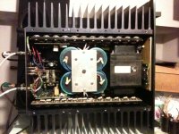
got a usher 1.5 200 watt per channel class a amp. no data on it anywhere. it's been passed around as a defective amp. It operates fine, then about 20 minutes later, the left channel cuts out. I'm the luck joe who figure out what was wrong with it....a few cold solders....I was able to pull a few bias resisters right out with little effort. So everything is all soldered up and the amp works fine. Remaining issues is to decide on a bias setting. Everyone who tried to fix it had their own ideas on what the bias should be. So for a 200 watt class A amp, what are recommendations. right now it's set to 50ma and the heat sinks are barely warm. The amp has 24 output transistors per channel and looks like it can fry some eggs. I have a pretty good AC line amp meter that can measure miliamps to 20amps. The amp at max power is supposed to draw 12 amps. Was thinking to adjust the bias until I get 80% of line draw or 9.6 amps. Unless there are other ideas. thanks for the input.
Attachments
Ok, here's a start.
Assuming it really is a class A amp (most that claim to be really are class AB), then also assuming it's only expected to run into 8 ohms (also unrealistic, as it should be able to stay class A down to at least 6 ohms, but we'll skip that particular difficulty) then the figures are....
200 Watts RMS translates to 400 W peak.
So the peak output current into 8R is , P = Isquared R
or Isq. = 400 over 8 =50
So I peak = root 50 = 7 (and a bit) amps.
This means your standing current is 3.5 Amps.
Incidentally you'll find for both channels the total heat dissiption at idle will be just a bit over 800 watts, maybe 850 to 900 Watts, hope you've got a big fan keeping it all cool.
If that is a stereo amp there is no way those heatsinks will be capable 200W Class A per channel.
At best, my guess is somewhere between 100W and 150W per channel. That is heat dissipated not musical power.
Assuming it has +/-60V dc rails, then 1 amp is about as much current as you will be able set the bias at.
You might be able to go higher but 1 amp is a good figure to start with.
For long term reliabiliy keep the heatsinks at or below 60 degrees C. If you don't have a thermocouple to measure the temperature the 5 second hand trick is just as good.
Could you give us the dimensions of those heatsinks. I am guessing they are somewhere around 350mm x 150mm x 50mm.
Last edited:
If that is a stereo amp there is no way those heatsinks will be capable 200W Class A per channel.
For long term reliabiliy keep the heatsinks at or below 60 degrees C. If you don't have a thermocouple to measure the temperature the 5 second hand trick is just as good.
I agree, no way that this is 200W pure Class-A per channel, not even if this would be the chassis/heatsinks for a mono amp. 200W Pure Class-A stereo would be a (or two) truly monstrous amp.
5 seconds touching works fine and corresponds to about or only slightly above 50°C.
Keep in mind that it also shouldn`t go much higher than this under more severe ambient air temperatures (hot summer!) as You might have now.
Isn't it a direct copy of a Threshold power amp ?
nice catch, based on your comment, I googled around and found that it is a clone of a "Threshold Stasis 2 Class A Power Amp" The "Threshold Stasis 3 Class A Power Amp" referenced as using a Nelson Pass design.
but yes, it looks identical to the Threshold Stasis 2 Class A Power Amp
so far, I set the bias to 60 ma's. As an additional step, after listening to the amp at 60ma's for a while, I added 4 12uf metal film bypass caps to the main power supply electrolytic's and that seemed to bring a sparkle to the sound.
Last edited:
You should first measure supply voltage it would give a way to figure out the power of the amp
ok, will do.
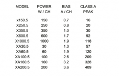
Im going to go with 70 ma's. there's a bais pot and both individual resistors on each transister of 1 ohm as well as a board resister of ten ohms. I can set the board to .7 amps, which directly translates to 70ma's on each transister. .7 is listed for a 150 watt amp. my amps is branded as a 200wpc amp. but as others have suggested, it may actually be less. it runs pretty lke warm at .6 or 60ma's so I have no issues with using .7 or 70ma's. btw, the author of the article i cliped the chart from is the designer of the amp. when I go back in, I'll measure the supply voltage.
Attachments
That amplifier is not a Class-a amp and don't be surprised if it sounds better at the lower bias, especially if you run it below 8 ohms..
I hate when that happens. it says class a all over the chasis, front, back, etc. they must mean that it was built with class a workmanship.
so the bias question continues.......
- Status
- This old topic is closed. If you want to reopen this topic, contact a moderator using the "Report Post" button.
- Home
- Amplifiers
- Solid State
- 200 watt Class A Amp bias recomendations