For those who don't like large heatsinks, this fan controller is a good choice.
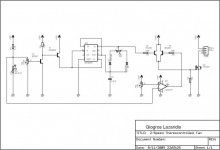
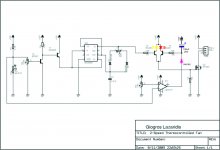
It is well explained here: Two Speed Temperature Fan PWM Controller - Electronic Circuit Schematics
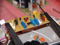
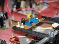
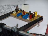
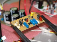
I slightly changed the circuit to use dual sensors and dual fans, and to be fed from a 24VDC input.
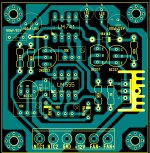
I need support to draw a decent PCB layout! Is alex mm around?
Cheers,
Max.
It is well explained here: Two Speed Temperature Fan PWM Controller - Electronic Circuit Schematics
I slightly changed the circuit to use dual sensors and dual fans, and to be fed from a 24VDC input.
I need support to draw a decent PCB layout!
Is alex mm around?Cheers,
Max.
Attachments
-
 DSC00292.JPG112.4 KB · Views: 1,239
 -
 DSC00293.JPG105.7 KB · Views: 1,159
 -
 DSC00294.JPG81.2 KB · Views: 1,107
 -
 DSC00295.JPG107.1 KB · Views: 1,061
 -
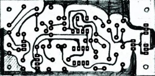 FanControl-PCB.jpg40.9 KB · Views: 1,045
 -
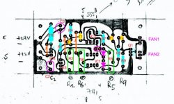 FanControlPCB-componentes.jpg38.1 KB · Views: 561
 -
 2speedthermofancontroller_1250021666.jpg32.9 KB · Views: 850
I've inserted a diode in series with opamp output, and then a capacitor from +12V.
It works fine, thanks. It is good to cleanup dirt!
I've also inserted two LEDs, between T3 and T4 collectors and +12V, in order to monitor controller's state. Yellow for mid speed, and red for full speed. So, during power-on, red LED is lit!
Thanks!
Regards,
Max.
It works fine, thanks. It is good to cleanup dirt!
I've also inserted two LEDs, between T3 and T4 collectors and +12V, in order to monitor controller's state. Yellow for mid speed, and red for full speed. So, during power-on, red LED is lit!
Thanks!
Regards,
Max.
Here (http://www.diyaudio.com/forums/soli...ur-solid-state-pics-here-166.html#post2397421) you can see some pics of the amp where this fan controller has been inserted in.
Regards,
Max.
Regards,
Max.
I designed my own little SMPS with a pot to control the speed.
I used a PIC micro with a PID technique.
It required very few components.
Class D, PIC... I see you are very skilled.
As you can see, counter-clockwise I only make use of quite simple stuff.
Due to knowledge limitations, of course. But there is way to learn. It would be nice to see your schematics and builds.
Regards,
Max.
Class D, PIC... I see you are very skilled.
As you can see, counter-clockwise I only make use of quite simple stuff.
Due to knowledge limitations, of course. But there is way to learn. It would be nice to see your schematics and builds.
Regards,
Max.
The schematics are very basic. Just a PIC driving a MOSFET with the output voltage potentially divided back into a PIC analogue port A2D converter.
The clever bit is the software in the PIC doing the SMPS.
I worked for a PIC consultancy for 13 years so know my way around the PICs.
If you can get away with a 555 timer then great.
My brother, who is an EE in Texas, USA, has presented me with a PIC programmer and a thick book to read. I just neeeeed to start.
As a very good computer programmer in the past, maybe I can climb this mountain...
I was originally a Z80 assembly programmer.
I was a bit horrified at the PICs when I first started using them after the Z80. However the PICs are cheap and have loads of options for interfacing.
I have a wealth of old PIC projects to draw on if I need to. Its easier than starting from scratch.
PCB
Hi alex mm in pcb of smartx21 is used 2 FAN, could be included in your drawing of pcb the second fan?
Congratulations
Hi Smartx21 here too...
Jotha
but not with empty hands
Alex.
Hi alex mm in pcb of smartx21 is used 2 FAN, could be included in your drawing of pcb the second fan?
Congratulations
Hi Smartx21 here too...
Jotha
can you pls share pcb copper side i want to try build this one..TYbut not with empty hands
Alex.
Hey Alex,
Thanks!!
I am confused as well.
So will I need 2 boards for 2 fans ?
Or can I just parallel 2 fans and connect them together ?
I am thinking of using this controller for a 100W amp, in which both channels are mounted on a single heatsink.
Thanks!!
Hi alex mm in pcb of smartx21 is used 2 FAN, could be included in your drawing of pcb the second fan?
Jotha
I am confused as well.
So will I need 2 boards for 2 fans ?
Or can I just parallel 2 fans and connect them together ?
I am thinking of using this controller for a 100W amp, in which both channels are mounted on a single heatsink.
- Status
- This old topic is closed. If you want to reopen this topic, contact a moderator using the "Report Post" button.
- Home
- Amplifiers
- Solid State
- 2 Speed Fan Controller