Member
Joined 2009
Paid Member
Moschfet, there are a couple of things to bear in mind. My simulation didn't necessarily balance the current contributions of the Class A and Class C stages properly - a change in resistor value(s) could address that. The other issue is crude way in which the Class C stage adds current to the load and how it's driven by the voltage drop across the output 'sense' resistor - it doesn't appear to be the most linear of methods.
I suspect that a more sophisticated method for combining the outputs of the A + C amplifiers is via a bridge, as used by the Quad 405 and later the Edwin (Elektor, 1970).
Wavebourn - you are a bit of a tease aren't you
I suspect that a more sophisticated method for combining the outputs of the A + C amplifiers is via a bridge, as used by the Quad 405 and later the Edwin (Elektor, 1970).
Wavebourn - you are a bit of a tease aren't you
Member
Joined 2009
Paid Member
moschfet,
your simulation file doesn't run as-is, it references device models that aren't included in the file. I find it best to include the models in the simulation file directly when posting on the forum. When I allowed spice to substitute it's default models for your simulation, it didn't work.
In my file, if you increase the series resistor between the base and emitter of the Class C boosters it's possible to get it to behave as intended - the load sees current from the Class A until that stage runs out of steam, then the Class C devices take over. However, it's still way too non-linear for my liking. It doesn't look as if it could hope to match a Class AB biassed output even if it were operated without feedback.
The current dumping design by Peter Walker (Quad) is a much more linear solution (unless Wavebourn knows better...) to combining a low power Class A with high power Class B/C - but it relies on error correction, it needs an error amplifier. I was hoping to achieve something fairly linear without an error amplifier.
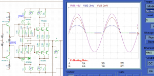
I'm not really sure about Broskie's conceptual schematics although I arrived at my configuration after trying a few options including the non-IMC concept that he proposed.I've attached a simple LTSpice simulation that can be played with, showing Class A, Class AB and Class AC (as per Broskie). They are all symmetrical. When the Class AC version kicks up to Class C the distortion profile is not nice. As far as I can see it's not functioning as it should, i.e. the Class C burners don't alleviate the Class A stage from going into clipping which I believe Broskie had intended with his 'impedance multiplier'. I don't think I've got is configured properly.
p.s. change the file extension from .txt to .asc in order to run this file under LTspice. The forum doesn't recognize the .asc extension (hint to administrators)
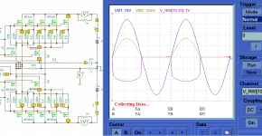
I'm not versed in LTSpice (I had my sims in TINA-TI) but I had a look around your ABC simulation and put my version in there for a comparo. The spectra is much cleaner, though I didn't optimise anything. The overlap zone appears to be very wide (A DC sweep would reveal much of this)
Certainly it can't touch Class-A but it seems to give your class-B example a run for its money
(.ASC as .txt attached)
Attachments
Member
Joined 2009
Paid Member
I'm not really sure about Broskie's conceptual schematics although I arrived at my configuration after trying a few options including the non-IMC concept that he proposed.
I'm not versed in LTSpice (I had my sims in TINA-TI) but I had a look around your ABC simulation and put my version in there for a comparo. The spectra is much cleaner, though I didn't optimise anything. The overlap zone appears to be very wide (A DC sweep would reveal much of this)
Certainly it can't touch Class-A but it seems to give your class-B example a run for its money
(.ASC as .txt attached)
Thanks 490!
Unfortunately, if you look at the current flow you will find that you've made a Class A + AB. The last pair of output devices is running in AB mode rather than Class C, being biassed off the drivers of the Class A stage. This is why the harmonics are much reduced (although they are mostly nasty H3, H5). I have looked at Class A + AB in the past and it works nicely; I believe Graham Maynard did something clever like this in his GEM amplifier.
...You can't .... Bigun. I'm afraid it is impossible ...


your simulation file doesn't run as-is, it references device models that aren't included in the file. I find it best to include the models in the simulation file directly when posting on the forum. When I allowed spice to substitute it's default models for your simulation, it didn't work.
O sorry, I forgot.
I hope this file is more useful, but now I am afraid, this is not what do you searching for. There are solutions with more high end ambitions. class-aa for example.
In my file, if you increase the series resistor between the base and emitter of the Class C boosters it's possible to get it to behave as intended - the load sees current from the Class A until that stage runs out of steam, then the Class C devices take over. However, it's still way too non-linear for my liking. It doesn't look as if it could hope to match a Class AB biassed output even if it were operated without feedback.
Now I got it.
But I like feedback or error correction to prevent distotion. My english is no so good, but do you looking for a solution that produce it self without a feedback very low distortion. And than you put a carefull feedback over the circuit.
Attachments
Member
Joined 2009
Paid Member
Yes, I was hoping not to use any feedback. I want to eliminate the need for compensation (which affects sonics) and also the escalation in higher order harmonics that -ve feedback encourages.
I'm in two minds whether feed-forward error correction as used in Quad current dumping (and by Wavebourn) suffers from these two 'defects' or not ?
On the other hand, this isn't my thread, I don't mean to push things in my preferred direction but i am hoping something interesting will develop from the discussions that mt490 has started.
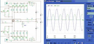
Hmm, the cross conduction does come quite close, though if we bring the Re of tha A back to 0.47 as your bias is designed for then reduce the centre bias we can go into C mode once again.Thanks 490!
Unfortunately, if you look at the current flow you will find that you've made a Class A + AB. The last pair of output devices is running in AB mode rather than Class C, being biassed off the drivers of the Class A stage. This is why the harmonics are much reduced (although they are mostly nasty H3, H5). I have looked at Class A + AB in the past and it works nicely; I believe Graham Maynard did something clever like this in his GEM amplifier.
The spectrum is still a little better than the previous AC but the 3rd and 5th aren't as good as the AB.
Just for reference, I post my cheap amp project story at output stages. The first one it appear to be class AC, when I am going to tweak it is still slow.
Then I change the output into somewhat canonic network, it is faster and better to handle but has some problem with high voltages.
Then Class AH used to my amplifier, resulting in less heat, better handle and faster and no high voltage problems.
It is privacy reason, right? then sorry for asking the details.
Then I change the output into somewhat canonic network, it is faster and better to handle but has some problem with high voltages.
Then Class AH used to my amplifier, resulting in less heat, better handle and faster and no high voltage problems.
It is not public domain, sorry. But I revealed key points already.
It is privacy reason, right? then sorry for asking the details.
Attachments
Member
Joined 2009
Paid Member
This is weird. after thinking about the current dumping option I found the 1980 paper by Vanderkooy and sent it to the printer.... awhile later my wife (who's not at all involved in my audio addiction) remarks, did you know your daughter plays with his grand daughter ? I just about fell off my chair !
Well it's a darn good read !
Well it's a darn good read !
This is weird. after thinking about the current dumping option I found the 1980 paper by Vanderkooy and sent it to the printer.... awhile later my wife (who's not at all involved in my audio addiction) remarks, did you know your daughter plays with his grand daughter ? I just about fell off my chair !
Well it's a darn good read !
Can you post a link, please?
I was just going to post the one link but the Google search gets things from different dates.
Results >current dumping 1980 Vanderkooy
Results >current dumping 1980 Vanderkooy
Well I was just searching for what Bigun was referring to but I'm pretty sure that's the one he means. They also published a two part article "Current Dumping: Does it work?" in the June and July 1978 issues of Wireless World.
I don't believe it is a coincidence: I made my "Non-Linear-Approximation-Cheating" design approximately at the same time. Akashic field indeed does exist. Paleontologists insist that an axe of the same form was made of different materials simultaneously in different remote locations on the Earth, as well as kitchenware of similar shapes...
Wellllll, the three of you are human after all. It seems natural to me that of tens (or hundreds) of thousands of people who grew up learning electronics (or any other discipline) in a world with a given state of the art, it's not weird that at least several of them would be poking around the same frontier. No?
On the other hand, right this very moment MILLIONS of people are dreaming. Just think of it!
On the other hand, right this very moment MILLIONS of people are dreaming. Just think of it!
Member
Joined 2009
Paid Member
Yes, this is the one !
It pretty much answers all my questions about this error correction business. Unfortunately, also confirming that you can't escape from using negative feedback at the same time.
Black's Feedforward: a sim
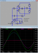
I worked up this "current dumping" Black's Feedforward sim from the jaes paper - sized for a headphone load since I'm using a op amp model with ~30mA output current limit
playing with the signal level it appears that it has the annoying property of increasing distortion as output level is reduced - the max % distortion occurs when the output level just starts to use the "dumper" Q for appreciable load current
feedback is necessary to implement the accurate correction amplifier in Black's Feedforward - I don't believe you can easily combine the sim's op amp and unbiased Q to do better in a "pure negative feedback" topology - so the Feedforward idea is valuable if you insist on "Class C+A"
the shown 2 V sine has ~0.01% output distortion, with the distortion growing to ~0.05% at around 200mV drive
it is hard to not comment on Bigun's several swipes at negative feedback:
use enough closed loop gain in a negative feedback amp with only smooth, low order nonlinearities and you get decreasing levels of harmonic distortion with harmonic order - not the 10-20 dB some "no-feedback" types may tepidly apply - it is easy to have >60 dB loop gain at all audio frequencies
there is no other practical way to obtain useful damping ratios - cathode, source, emitter followers are all 100% (local) negative feedback circuits - there are no "inherently low output impedance" amplifying devices
the "no-feedback" crowd's beloved Triode vacuum tube has loads of internal negative feedback - directly causing the observed plate resistance - a tube without internal feedback is a correctly biased Pentode
negative feedback is a foundational principle and should be properly understood and used correctly - ignore audiophool mythology if you want to learn how to design sucessful circuits
Attachments
Last edited:
the "no-feedback" crowd's beloved Triode vacuum tube has loads of internal negative feedback - directly causing the observed plate resistance - a tube without internal feedback is a correctly biased Pentode
Triode don't have non-linearities of higher orders that are essential to devices linearized by negative feedback.
How can you explain that, if it's a pentode with internal negative feedback?
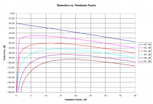
Here is an example of what happens when negative feedback is applied to the device with 10% of distortions of 2'nd order only:
Attachments
Last edited:
- Status
- This old topic is closed. If you want to reopen this topic, contact a moderator using the "Report Post" button.
- Home
- Amplifiers
- Solid State
- Analysing power requirements (Class-A+C/AB2)