

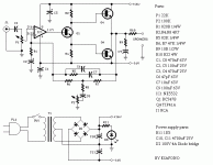
Stee,
your output stage will not work like its shown.
Ask yourself what happens to the current flow in the output transistors when the output of the op-amp swings positive . . .
And then, when it swings negative . . .
Your are also going to have a LOT of oscialltion problems if you use an amplifer stage (Q1) after the op-amp. The complicated feedback network is not going to help you here either.
Get yourself a copy of LTSpice and simulate your circuit first, then post your results up and we can try to steer you towards a workable design - you learn quickly like that as well.
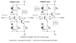
Hi Stee.
while I'm sure the other responses you've had will undoubtedly help you in the long run, it won't help you see that your circuit will burn up as soon as you connect a load to it.
Your circuit, as it stands will have Q4 permanently switched ON and as soon as you attach a load, will apply a -ve DC voltage to that load and destroy it.
Assuming it is a speaker, you might hear one very loud CLICK as the coil and cone slams to one side or the other and starts smoking!
This because your R4 is clamped to Vbe of Q4 and the output of the Op Amp is clamped at approximately 2 x Vbe above the negative rail.
Changing Q2 to a PNP as suggested above will help but you'll still have about 3 - 4mA into the base of Q4, resulting in a large negative offset.
You really need to Google for BJT output stages to sort this out.
By the way, complementary output stages produce VERY good results.
Have fun and happy designing,
Sandy
- Status
- This old topic is closed. If you want to reopen this topic, contact a moderator using the "Report Post" button.
- Home
- Amplifiers
- Solid State
- SEPP LITTLE SOLID AMP