This is not a good place to use a CCS, as sajti says. You already have poor DC offset stability, and CCS would make it much worse.
Much better to add a CF/EF so that you can drive the 28K input impedance - it is not that low anyway! Maybe your trouble comes from using an SRPP in the previous stage, as this has high output impedance and poor driving capability unless carefully designed. Scrap the SRPP, and instead use a common-cathode followed by a CF which bootstraps the anode load.
Much better to add a CF/EF so that you can drive the 28K input impedance - it is not that low anyway! Maybe your trouble comes from using an SRPP in the previous stage, as this has high output impedance and poor driving capability unless carefully designed. Scrap the SRPP, and instead use a common-cathode followed by a CF which bootstraps the anode load.
Member
Joined 2009
Paid Member
There will be lot of problem with the DC stability, if You apply 2 CCS instead of the resistors. You can use bootstrapping, or parallel CCS+resistor, if You need higher input impedance.
Sajti
Perhaps my botchup design (post19) could be a solution too ?
http://www.diyaudio.com/forums/solid-state/159780-biguns-botch-up-amplifier.html
Hello,
thanks in advance for the first replies.
The difficulty came because I don't want to change the circuit, as said, (especially I do want to use the diodes for biasing and not a Vbe multiplier) and I don't want to use two capacitors to enter, like in sajti schematic, but I want to enter at a certain point in the diodes string, as it is now.
I just want (would like") to stabilize the current flow into the diodes, to the aim that the signal passing through them will not be negatively infuenced by the continuous (small) variance, as it is now with the two resistors.
to stabilize the current flow into the diodes, to the aim that the signal passing through them will not be negatively infuenced by the continuous (small) variance, as it is now with the two resistors.
And, as a consequence, an higher input impedance is *of course* very welcome! The output offset is not a problem.
Probably, stating this, the circuits that fits better is the one proposed by Elvee (Post #5).
Any further comment on this one?
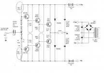
Just to calculate component values I will use as a power voltage 60+60volt stabilized (and not 42+42 as in the schematic), and I can use 2SD669A/2SB649A for the two CCS proposed by Elvee.
(I will use the same as pre-drivers, the MJE15032-15033 as drivers and the 2SC3264/2SA1295 as output).
Thanks a lot in advance!
GM
thanks in advance for the first replies.
The difficulty came because I don't want to change the circuit, as said, (especially I do want to use the diodes for biasing and not a Vbe multiplier) and I don't want to use two capacitors to enter, like in sajti schematic, but I want to enter at a certain point in the diodes string, as it is now.
I just want (would like
to stabilize the current flow into the diodes, to the aim that the signal passing through them will not be negatively infuenced by the continuous (small) variance, as it is now with the two resistors.And, as a consequence, an higher input impedance is *of course* very welcome! The output offset is not a problem.
Probably, stating this, the circuits that fits better is the one proposed by Elvee (Post #5).
Any further comment on this one?
Just to calculate component values I will use as a power voltage 60+60volt stabilized (and not 42+42 as in the schematic), and I can use 2SD669A/2SB649A for the two CCS proposed by Elvee.
(I will use the same as pre-drivers, the MJE15032-15033 as drivers and the 2SC3264/2SA1295 as output).
Thanks a lot in advance!
GM
Last edited:
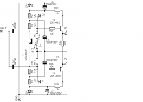
You can use the bootstrapping together with the diode string. Personally I don't like the diode string, because it's not easy to mount on the heatsink.
The zener is not necessary if You use regulated PSU. Than You can increase the input resistors from 22k to 27k. The 2.2k+100uF filter would be good to keep.
Sajti
The zener is not necessary if You use regulated PSU. Than You can increase the input resistors from 22k to 27k. The 2.2k+100uF filter would be good to keep.
Sajti
Attachments
brute force would be electrolytics bypassing diode dyamic impedance - need 2x ~ 1000uF from signal in to each input Q base - Al electrolytics (or even Ta) won't be as bad as diode distortion
the split R, C bootstrap can give MOhm AC Z - although you may want to take off from pre/driver Q emitters to reduce load dependance - if your supply is OK I wouldn't bother with subregualtion
the split R, C bootstrap can give MOhm AC Z - although you may want to take off from pre/driver Q emitters to reduce load dependance - if your supply is OK I wouldn't bother with subregualtion
Last edited:
brute force would be electrolytics bypassing diode dyamic impedance - need 2x ~ 1000uF from signal in to each input Q base - Al electrolytics (or even Ta) won't be as bad as diode distortion
Bypass is good idea. I use double coupling capacitors, this solution does the bypass as well on my Vbe multiplier.
the split R, C bootstrap can give MOhm AC Z - although you may want to take off from pre/driver Q emitters to reduce load dependance - if your supply is OK I wouldn't bother with subregualtion
The predriver trick doesn't work unfortunately. I did it, and found 3-4V DC offset, without load. No oscillation, no any other problem, only the offset. If I connect the 4ohm load, the offset falls to 100mV. But finally I avoid the predriver solution. The output bootstrapping gives 20-25times increase of the input impedance.
sajti
Thank you very much!
All power supplies are stabilized and separated for pre-driver+driver and final bjts.
I would try not to add any further capacitor on the signal path, and no feedback.
May you please comment the Elvee circuit (Post 5). Do you have any suggestion to improve it or I can just implement it as it is presented? What will be here approximately the input impedance?
Thanks a lot again,
GM
May you please comment the Elvee circuit (Post 5). Do you have any suggestion to improve it or I can just implement it as it is presented? What will be here approximately the input impedance?
I can't help You if it works properly. You should try it. The iput impedance will be 750kohm parallel with the input impedance of the triple darlington. This is not easy to predict, because it depended by the BJT-s.
Sajti
Hello,
Elvee, everybody, any other kind advice or comment on the Elvee schematic?
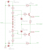
For example is it possible to use a LED/2 LEDs to avoid the C1 & C2 in the Elvee schematic (Post #5)?
Or, are we shure the two CCS will not create problems if they conduct a (also slightly)different current?
Thanks!
GM
Elvee, everybody, any other kind advice or comment on the Elvee schematic?
For example is it possible to use a LED/2 LEDs to avoid the C1 & C2 in the Elvee schematic (Post #5)?
Or, are we shure the two CCS will not create problems if they conduct a (also slightly)different current?
Thanks!
GM
For example is it possible to use a LED/2 LEDs to avoid the C1 & C2 in the Elvee schematic (Post #5)?
You will lose all the practical advantages of Elvee's circuit with LEDs. It works only with resistors.
Or, are we shure the two CCS will not create problems if they conduct a (also slightly)different current?
You found the most critical problem of the 2ccs version. 1% difference means the output will goes up or down to the rail. Use only ccs to bias the input stage is absolutely wrong solution. You have to use some resistor, or servo.
sajti
Hi,
so in the end: better 2x CCS with this up and down problem, or keep the 2 resistors as in the original schematic?
Thanks!
I think You don't understand the situation. The "2xCCS with up and down problem" means that Your amplifier doesn't work!
Not necessary to keep the original version, because it has very low input impedance. There was 2 useful upgrade...
Sajti
- Status
- This old topic is closed. If you want to reopen this topic, contact a moderator using the "Report Post" button.
- Home
- Amplifiers
- Solid State
- implement CCS on a BJT darlington buffer